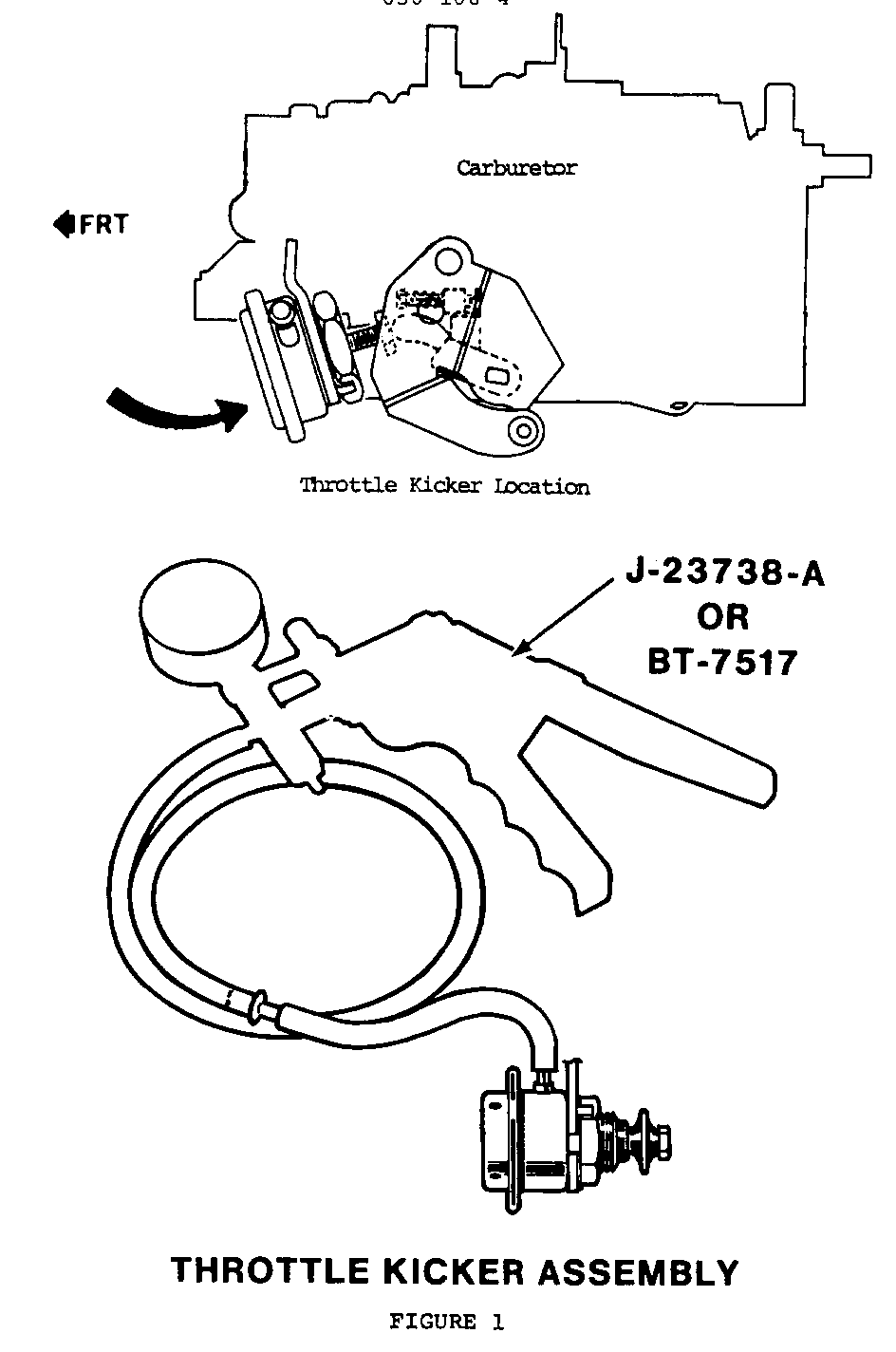
THROTTLE LEVEL ACTUATOR (THROTTLE KICKER)

VEHICLES AFFECTED: 1985-86 C, K, G and P Model Light Duty Trucks With 4.3L, 5.0L , 5.7L Engines and 1985 M Van With 4.3L Engine
A change has been made in the Throttle Lever Actuator (Throttle Kicker) Checking Procedure found in the 1985 and 1986 Light Duty Truck Service Manuals. The current checking procedure, found in sections 6E8-109 (1985) and 6E8-105 (1986), does not differentiate between the V6 and V8 engines. This may lead to unnecessary throttle kicker replacement on the V6 engine.
The throttle kicker used on certain Federal and California V6 engines is used to maintain a stable idle speed under varying engine load conditions. It operates on the manifold vacuum available at idle and does not have an internal plunger return spring, but instead relies on throttle return spring pressure to retract the plunger. The California HD V8 engines (Codes M and W) use a throttle kicker for decel emission control, and operate on higher decel manifold vacuum. The kicker designed for these applications uses an internal plunger return spring that causes the plunger to retract automatically when vacuum is released. These differences in design necessitate different checking procedures.
The current checking procedure in the 1985 and 1986 Light Duty Service Manual is correct for the California HD v8 engines. An additional procedure is required for the Federal and California V6 engines (listed below).
Also included is a chart of the carburetor specifications for 1986 4BBL applications that are not included in the 1986 Service Manual (see Chart No. 1).
THROTTLE KICKER CHECKING PROCEDURE (V6 FEDERAL AND CALIFORNIA EMISSIONS - ENGINE VIN CODE N)
1. With engine off (not running), hold throttle half way open to allow throttle kicker plunger to fully extend for testing.
2. Use J-23738-A or BT-7517, hand operated vacuum pump to apply 20 in. Hg (68 kPa) vacuum to the throttle kicker (see Figure No. 1).
Apply finger pressure to the plunger to see if it has extended fully. If not, replace the throttle kicker plunger.
Observe vacuum gauge: Vacuum should hold for at least twenty seconds. If not, replace throttle kicker.
3. Release vacuum to the kicker.
Apply finger pressure to the plunger, to move it to its retracted position. If plunger will not retract, replace the kicker.
The throttle kicker used on the V6 engine by design does not have an internal plunger return spring. When vacuum is released from kicker, the plunger will not retract on its own. This unit requires throttle lever pressure to retract the plunger.
MODEL M4MC/M4ME CARBURETORS FAST CARBU- FLOAT PUMP PUMP AIR CHOKE IDLE RETOR LEVEL ROD ROD VALVE COIL CAM PART mm (inches) SETTING LOCA- SPRING LEVER (CHOKE NO. +/- 2/32" mm(inches) TION (Turns) ROD) -- ---------- ----------- ---- ------- ----- +/-2.5 DEG ---------- 17086044 13.5 (17/32) 7.0 (9/32) INNER 7/8 .120 20 DEG 17086045 13.5 (17/32) 9.5 (3/8) OUTER 7/8 .120 20 DEG 17086046 13.5 (17/32) 7.0 (9/32) INNER 7/8 .120 20 DEG 17086047 13.5 (17/32) 9.5 (3/8) OUTER 718 .120 20 DEG 17086048 13.5 (17/32) 7.0 (9/32) INNER 1/2 .120 20 DEG 17086053 13.5 (17/32) 9.5 (3/8) OUTER 1/2 .120 20 DEG 17086054 13.5 (17/32) 7.0 (9/32) INNER 1/2 .120 20 DEG 17086055 13.5 (17132) 9.5 (318) OUTER 1/2 .120 20 DEG
CARBU- VACUUM VACUUM AIR UNLOADER RETOR BREAK BREAK VALVE +/- 4 DEG PART FRONT REAR ROD NO. +/- 2.5 DEG +/- 3.5 DEG mm(Inches) -- ----------- ----------- ---------- ---------- 17086044 26 DEG 38 DEG 0.6 (.025) 39 DEG 17086045 26 DEG 36 DEG 0.6 (.025) 39 DEG 17086046 26 DEG 38 DEG 0.6 (.025) 39 DEG 17086047 26 DEG 36 DEG 0.6 (.025) 39 DEG 17086048 26 DEG 36 DEG 0.6 (.025) 39 DEG 17086053 26 DEG 36 DEG 0.6 (.025) 39 DEG 17086054 26 DEG 36 DEG 0.6 (.025) 39 DEG 17086055 26 DEG 36 DEG 0.6 (.025) 39 DEG
MODEL E4ME CARBURETOR
IDLE AIR MIXTURE IDLE VALVE CHOKE CHOKE CARBU- FLOAT LEAN NEEDLE AIR SPRING STAT LINK RETOR LEVEL MIXTURE (NO. OF BLEED (NO.OF LEVER CAM NUMBER +/- 2/32" SCREW TURNS) VALVE TURNS) +/- 2.5 DEG ------ --------- ----- ------ ----- ------ ----- ----------- 17086057 18/32 1.304G SEE 1.756G 7/8 .120 20 DEG (14.0 mm) NOTE Gage 17086058 (18132 1.304G SEE 1.756G 7/8 .120 20 DEG (14.0 mm) NOTE Gage
CARBU- VACUUM VACUUM RETOR BREAK BREAK AIR UN- NUMBER FRONT REAR VALVE LOADER ------ +/-2.5 DEG +/-3.5 DEG ROD +/- 4 DEG ---------- ---------- --- --------- 17086057 26 DEG 36 DEG .025 39 DEG
17086058 26 DEG 36 DEG .025 39 DEG
NOTE: Preset 3 Turns, Final Adjustment On Vehicle
CHART NO. 1

General Motors bulletins are intended for use by professional technicians, not a "do-it-yourselfer". They are written to inform those technicians of conditions that may occur on some vehicles, or to provide information that could assist in the proper service of a vehicle. Properly trained technicians have the equipment, tools, safety instructions and know-how to do a job properly and safely. If a condition is described, do not assume that the bulletin applies to your vehicle, or that your vehicle will have that condition. See a General Motors dealer servicing your brand of General Motors vehicle for information on whether your vehicle may benefit from the information.
