For 1990-2009 cars only
Removal Procedure
- Disconnect the negative battery cable. Refer to Battery Negative Cable Disconnection and Connection in Engine Electrical.
- Remove the drive belt. Refer to Drive Belt Replacement .
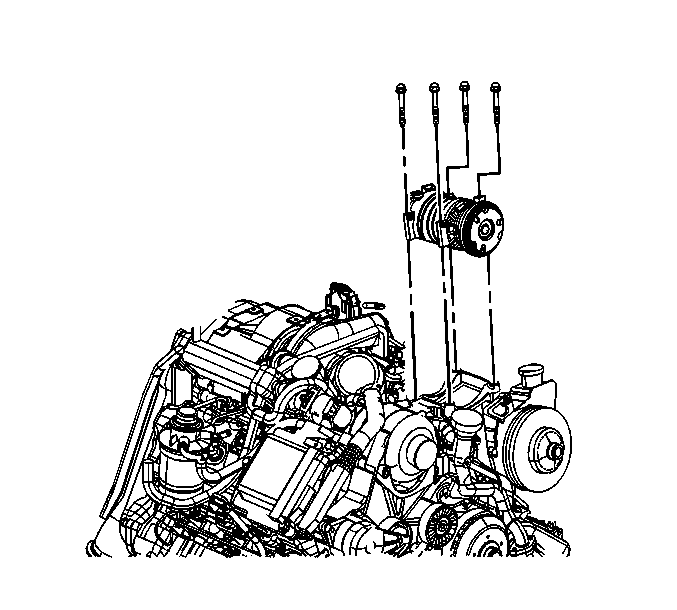
- If equipped, remove the auxiliary generator. Refer to Auxiliary Generator Replacement in Engine Electrical.
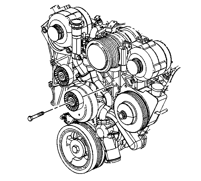
- If equipped with dual generators, remove the bolt from the left side idler pulley (smooth pulley).
- Remove the idler pulley.
- Disconnect the air conditioning (A/C) compressor clutch electrical connector.
- Disconnect the A/C cut out switch electrical connector.
- Remove the A/C compressor bolts.
- Move the A/C compressor with the hoses attached to the right side of the engine compartment.
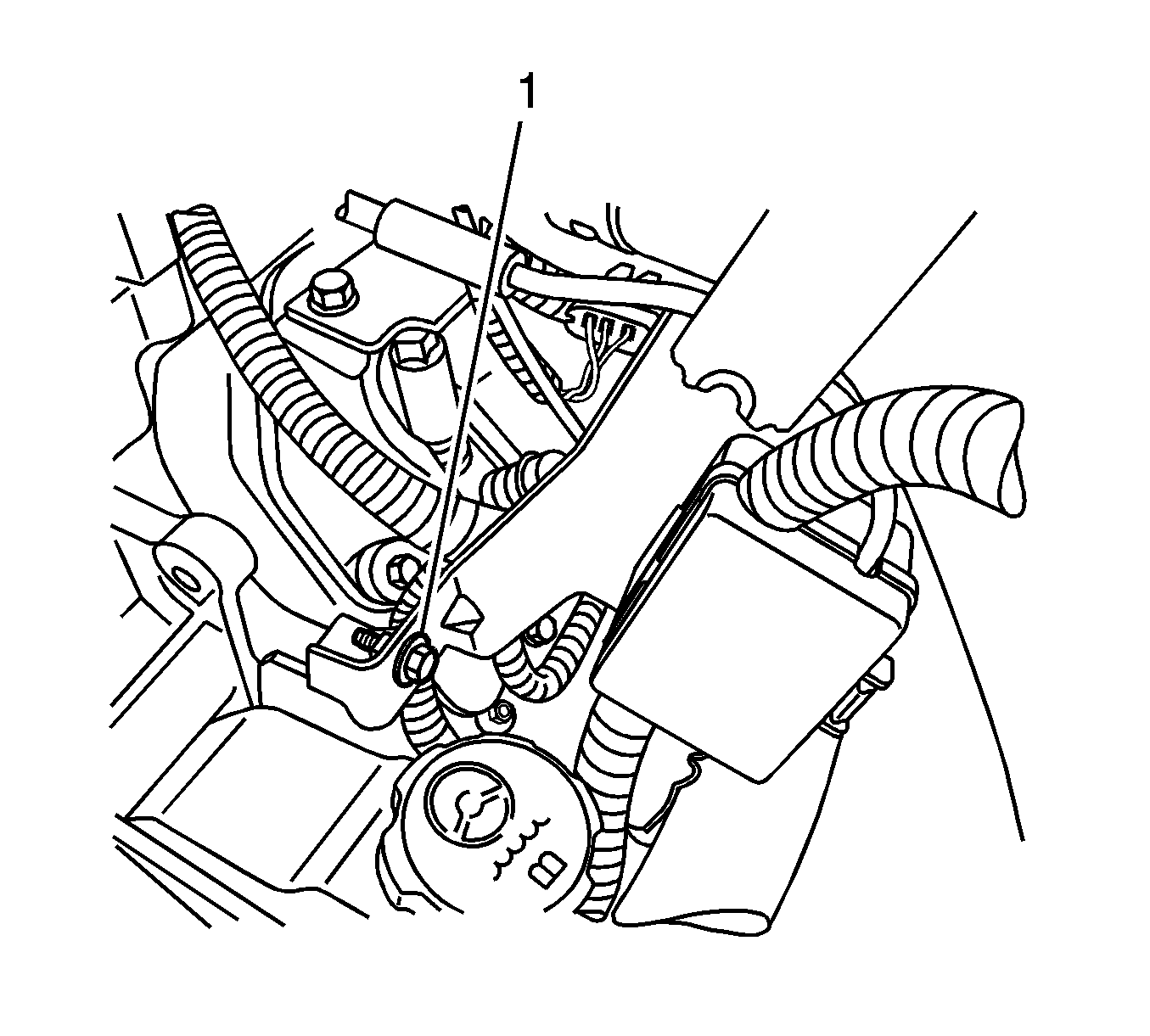
- Remove the positive cable junction block to power steering pump bolt (1).
- Secure the junction block out of the way.
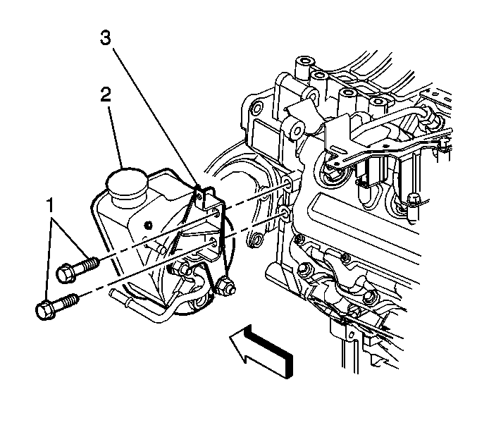
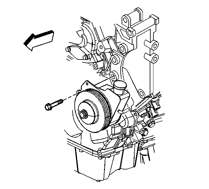
- Remove the rear power steering pump bracket bolts (1).
- Remove the power steering pump front bracket bolt.
- Move and secure the power steering pump out of the way. The hoses and battery cables can remain attach to pump.
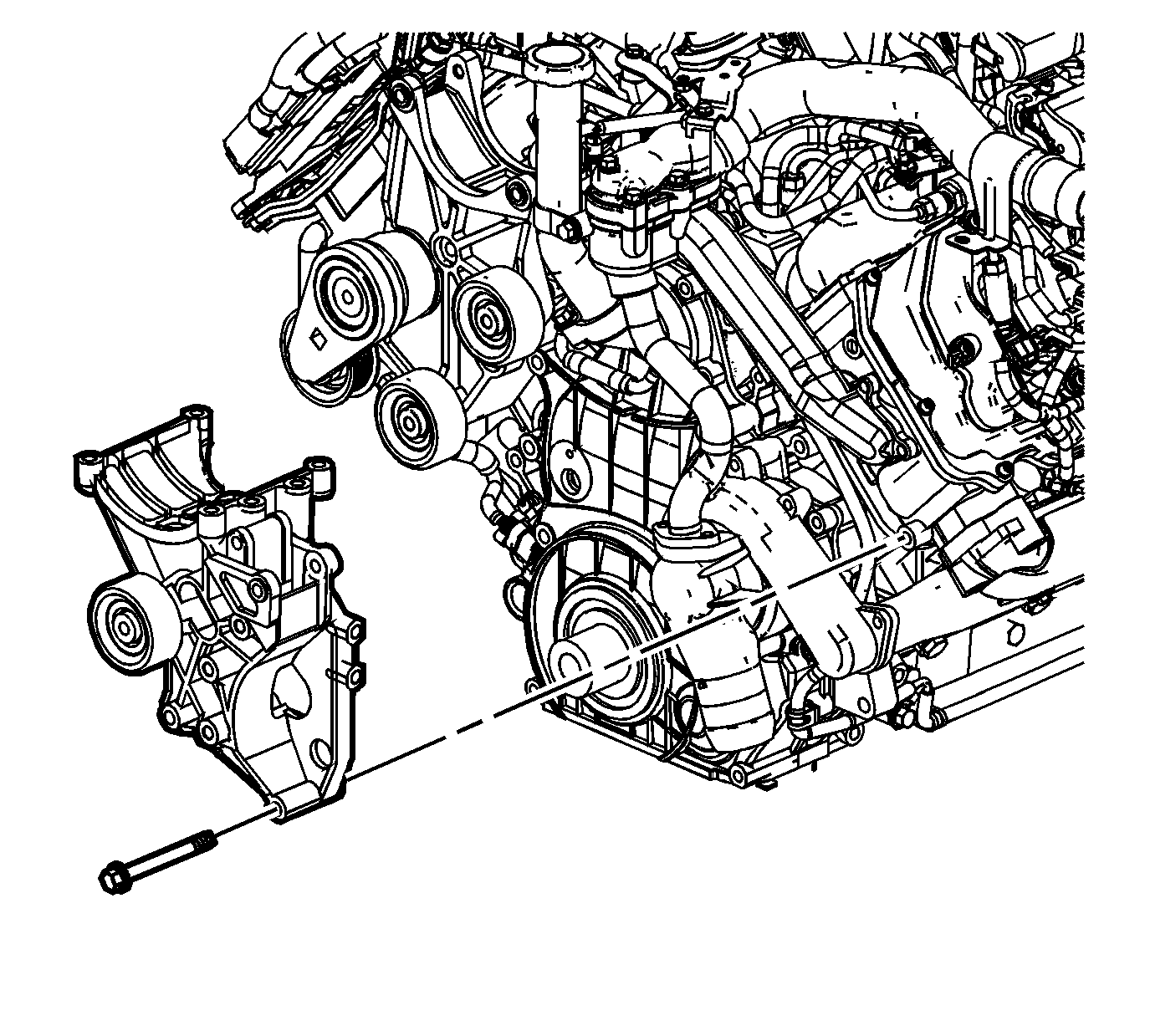
- Remove the A/C compressor and power steering pump bracket bolts.
- Remove the A/C compressor and power steering pump bracket.
Installation Procedure
- Position the A/C compressor and power steering pump bracket.
- Install the A/C compressor and power steering pump bracket bolts.
- Install the power steering pump and loosely install the front bracket bolts.
- Loosely install the rear power steering pump bracket bolts (1).
- Tighten the front bracket bolts to 50 N·m (37 lb ft).
- Tighten the rear bracket bolts to 50 N·m (37 lb ft).
- If equipped with dual generators, install the left side idler pulley and bolt.
- Install the auxiliary generator. Refer to Auxiliary Generator Replacement in Engine Electrical.
- Install the battery cable junction block and bolt (1).
- Position the A/C compressor.
- Install the A/C compressor bolts.
- Connect the A/C cut out switch electrical connector.
- Connect the A/C clutch electrical connector.
- Install the drive belt. Refer to Drive Belt Replacement .
- Connect the negative battery cable. Refer to Battery Negative Cable Disconnection and Connection in Engine Electrical.
Notice: Refer to Fastener Notice in the Preface section.
Tighten
Tighten the bolts to 46 N·m (34 lb ft).
Important: Tighten the front bracket bolts before the rear bracket bolts to ensure pulley alignment.
Tighten
Tighten
Tighten the bolt to 43 N·m (32 lb ft)
Tighten
Tighten the bolt to 9 N·m (80 lb in).
Tighten
Tighten the bolts to 50 N·m (37 lb ft).
