GM Service Manual Online
For 1990-2009 cars only
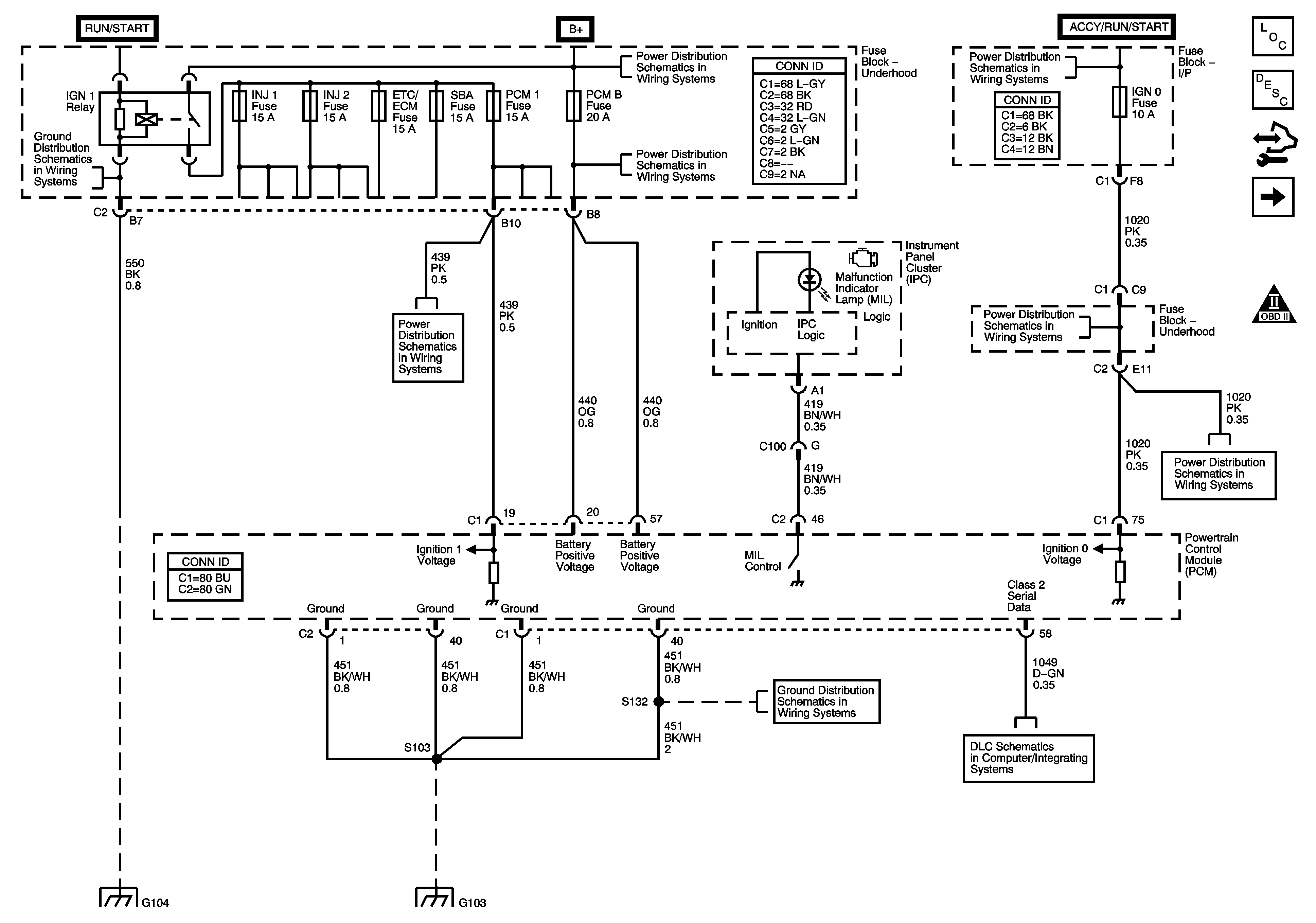
Figure 1:

Module Power, Ground, Serial Data, and MIL

Object Number: 1542622  Size: FS
Master Electrical Component List
Powertrain Control Module Description
Control Module References
Engine Data Sensors - 5-Volt and Low Reference
Engine Controls Schematic Icons
G104, G106, G107 and G110
ETC/ECM, INJ 1, INJ 2, PCM 1, and SBA Fuses - Gas
B+ Bar Bus
AUX PWR, AUX PWR 2, DDM, ECC, LBEC 2, LOCKS, PCM B, and PDM Fuses
Ignition Switch - START, RUN, and ACC/RUN/START Bus Bars and IGN A and CRANK Fuses
IGN 0, RR WPR, SEO ACCY, TBC ACCY, TBC IGN 0, and WS WPR Fuses
G104, G106, G107 and G110
G103 - Gas
G103 - Gas
Power, Ground, DLC and Splice Pack SP 205
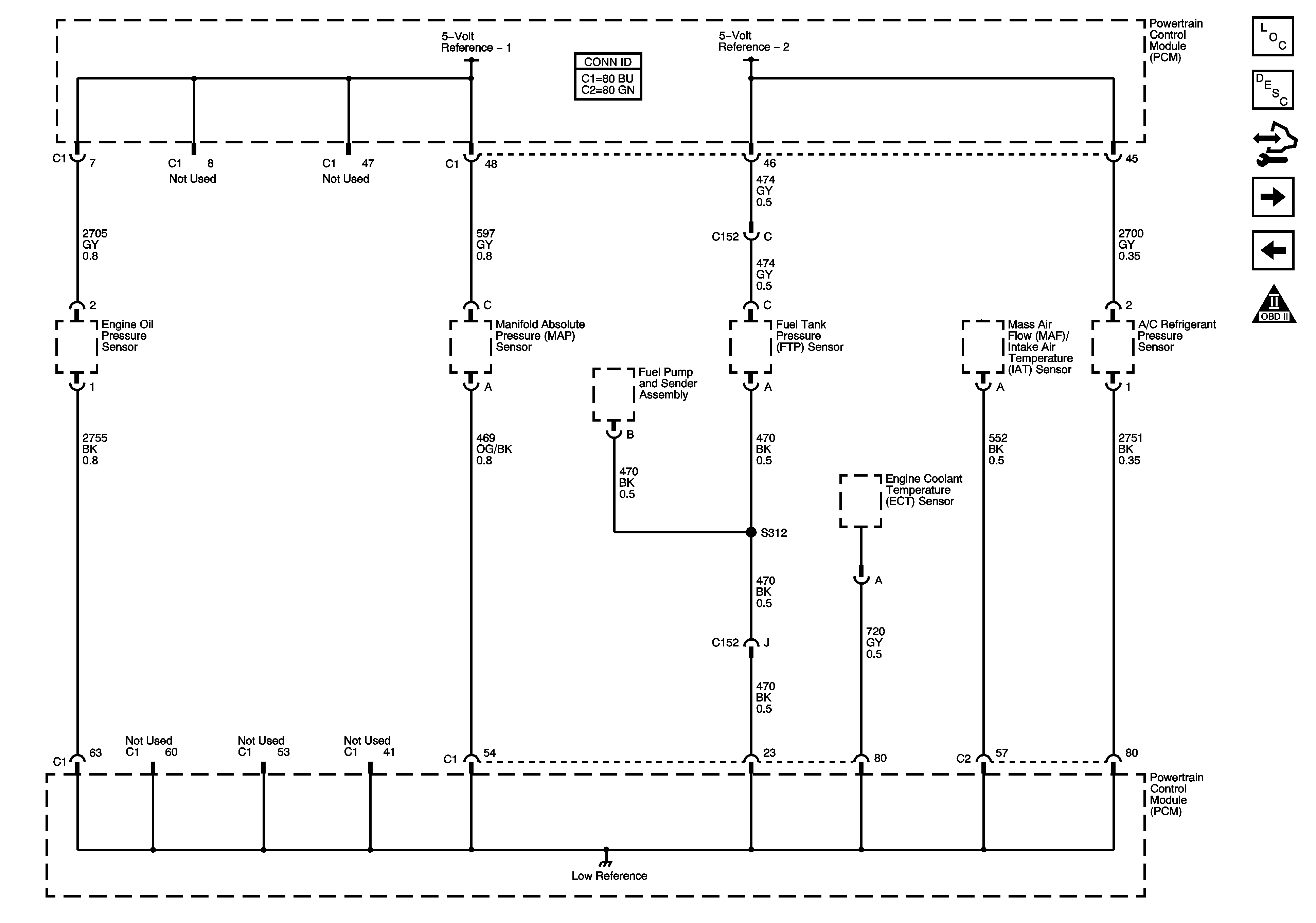
Figure 2:

Engine Data Sensors - 5-Volt and Low Reference


Object Number: 1542623  Size: FS
Master Electrical Component List
Powertrain Control Module Description
Control Module References
Engine Data Sensors - Pressure, Temperature, MAF, and VSS
Module Power, Ground, Serial Data, and MIL
Engine Controls Schematic Icons
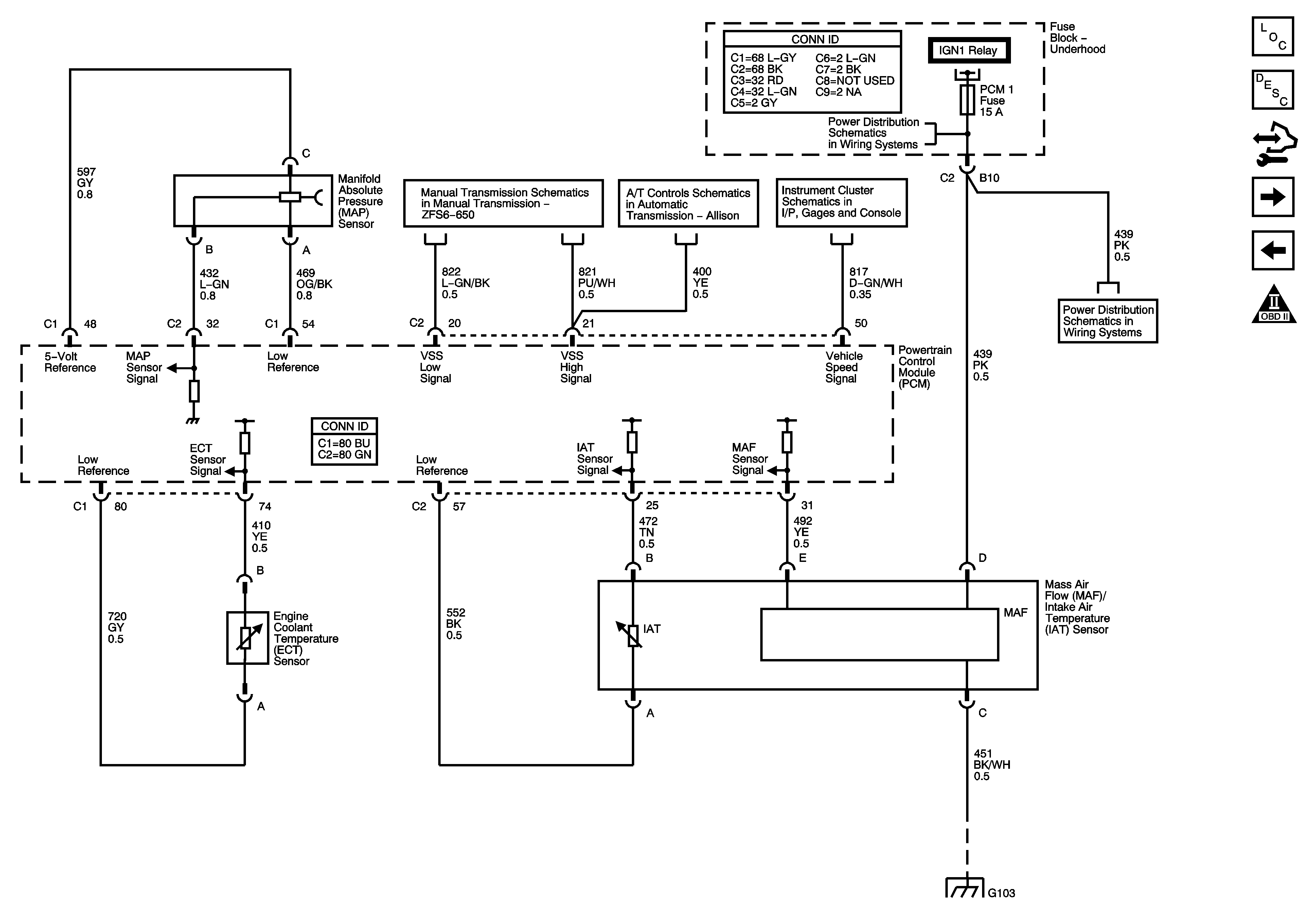
Figure 3:

Engine Data Sensors - Pressure, Temperature, MAF, and VSS


Object Number: 1542624  Size: FS
Master Electrical Component List
Air Intake System Description
Control Module References
Engine Data Sensors - Oxygen Sensors
Engine Data Sensors - 5-Volt and Low Reference
Engine Controls Schematic Icons
Manual Transmission ZF S6-650
Speed Sensors and PNP Switches
ETC/ECM, INJ 1, INJ 2, PCM 1, and SBA Fuses - Gas
G103 - Gas
Figure 4:

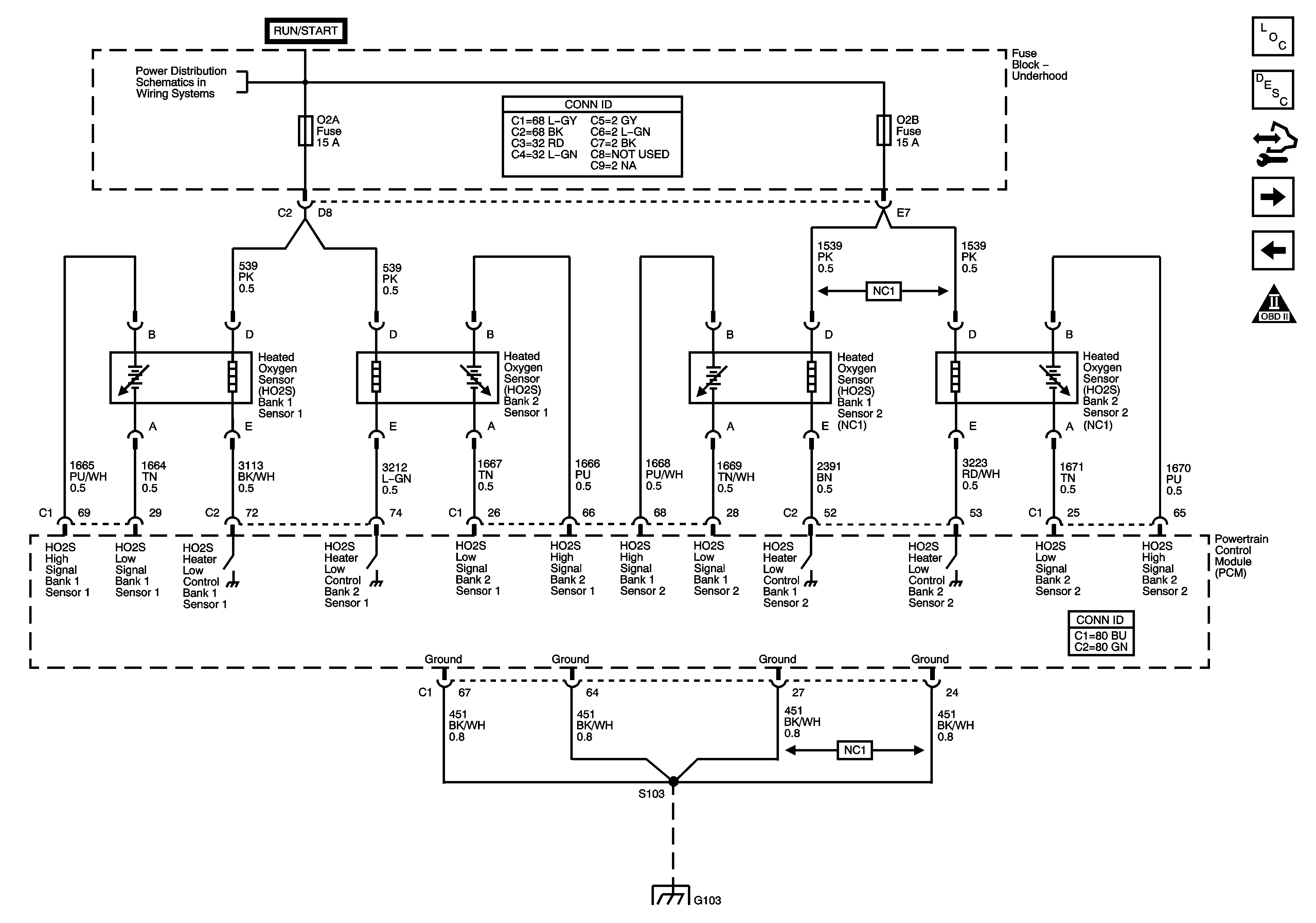
Engine Data Sensors - Oxygen Sensors


Object Number: 1542625  Size: FS
Master Electrical Component List
Powertrain Control Module Description
Control Module References
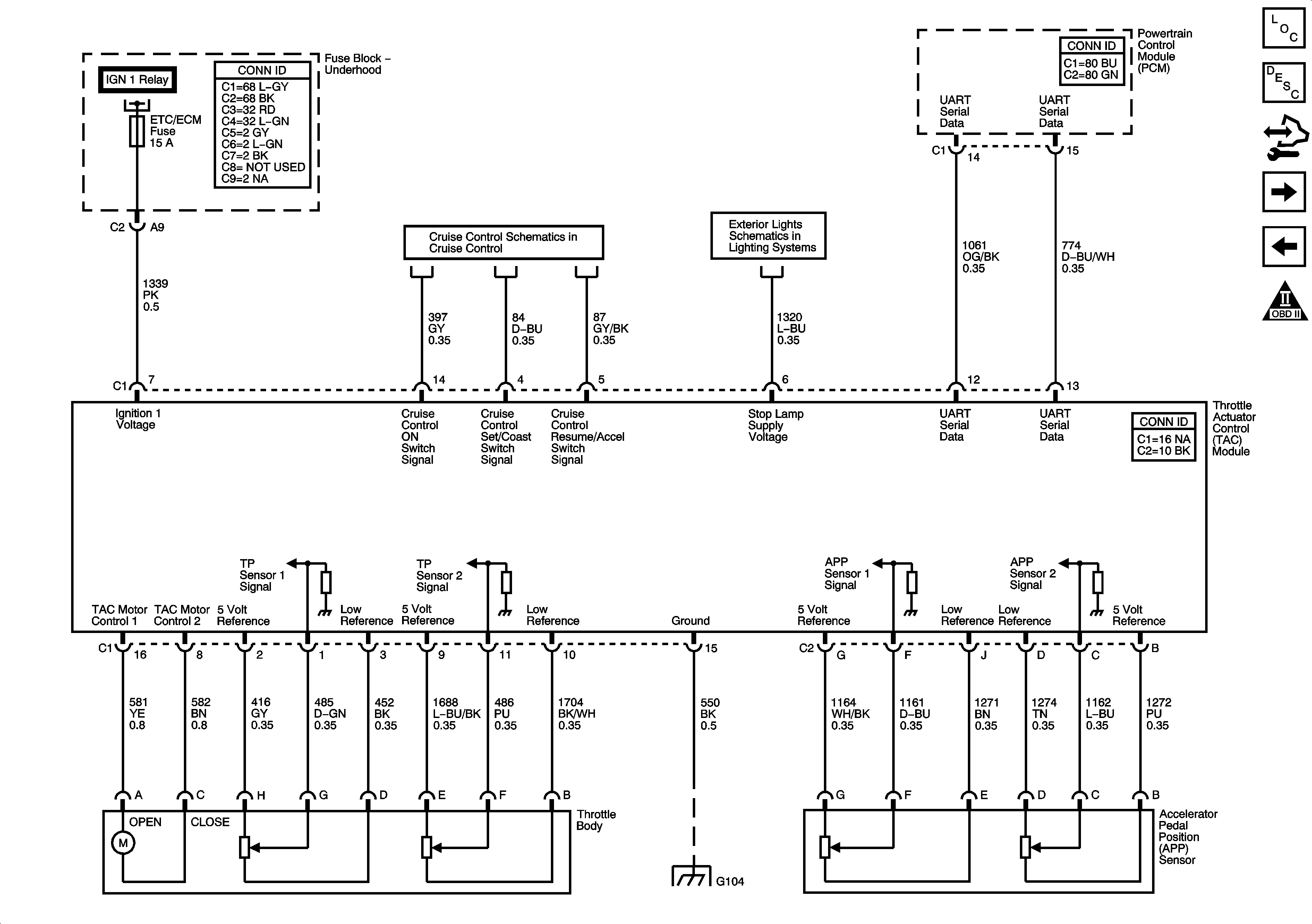
Engine Data Sensors - Electronic Throttle Control
Engine Data Sensors - Pressure, Temperature, MAF, and VSS
Engine Controls Schematic Icons
Ignition Switch - ACC/RUN and RUN/START Bus Bars and IGN B Fuse
G103 - Gas
Figure 5:

Engine Data Sensors - Electronic Throttle Control


Object Number: 1538792  Size: FS
Master Electrical Component List
Throttle Actuator Control (TAC) System Description
Control Module References
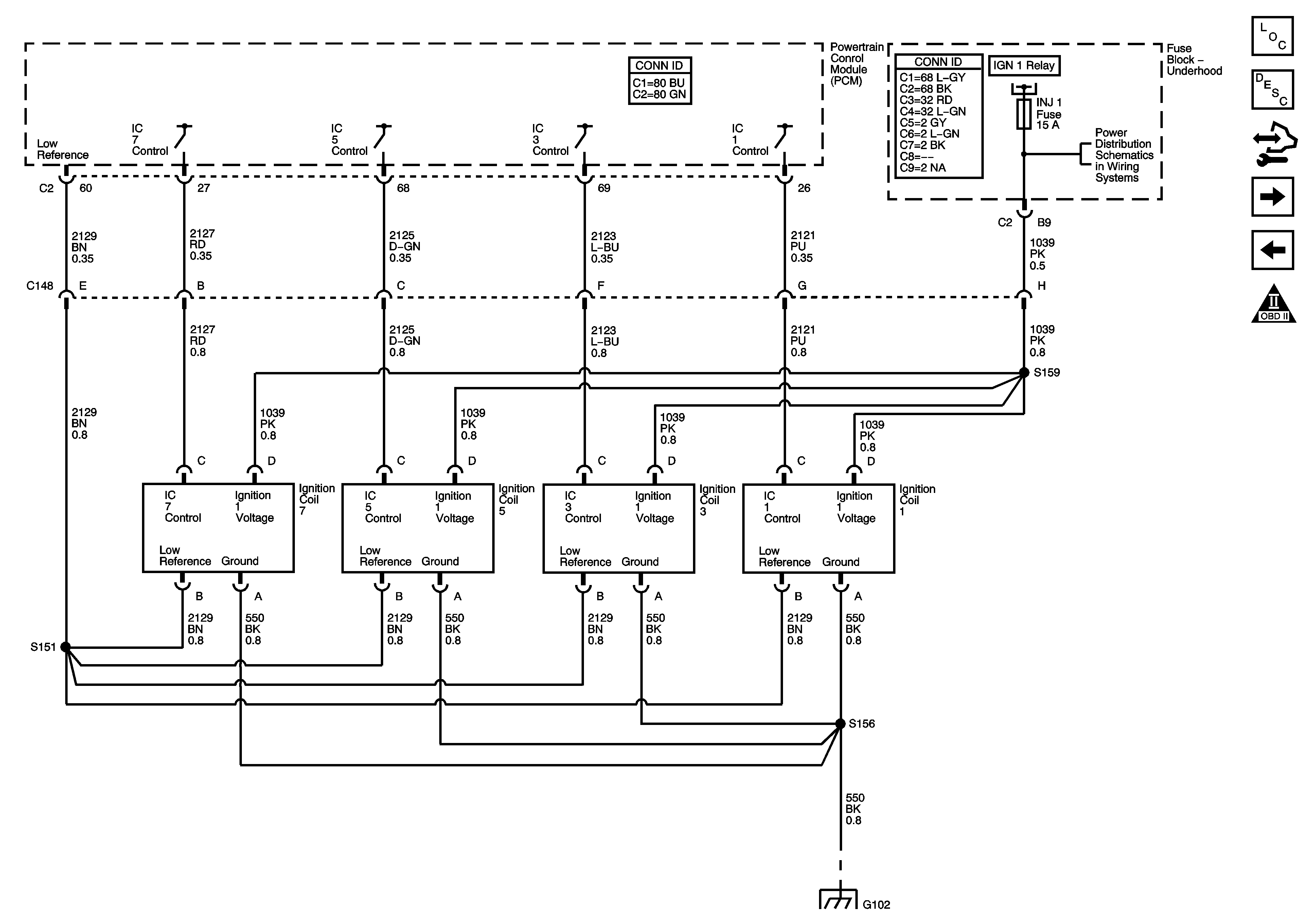
Engine Controls - Ignition System Coils 1, 3, 5, and 7
Engine Data Sensors - Oxygen Sensors
Engine Controls Schematic Icons
Module Power, Ground, Serial Data, and MIL
4.8L, 5.3L 6.0L, and 8.1L
Stop Lamps - GMC
G104, G106, G107 and G110
Figure 6:

Ignition Controls - Ignition System Coils 1, 3, 5, and 7


Object Number: 1542626  Size: FS
Master Electrical Component List
Electronic Ignition (EI) System Description
Control Module References
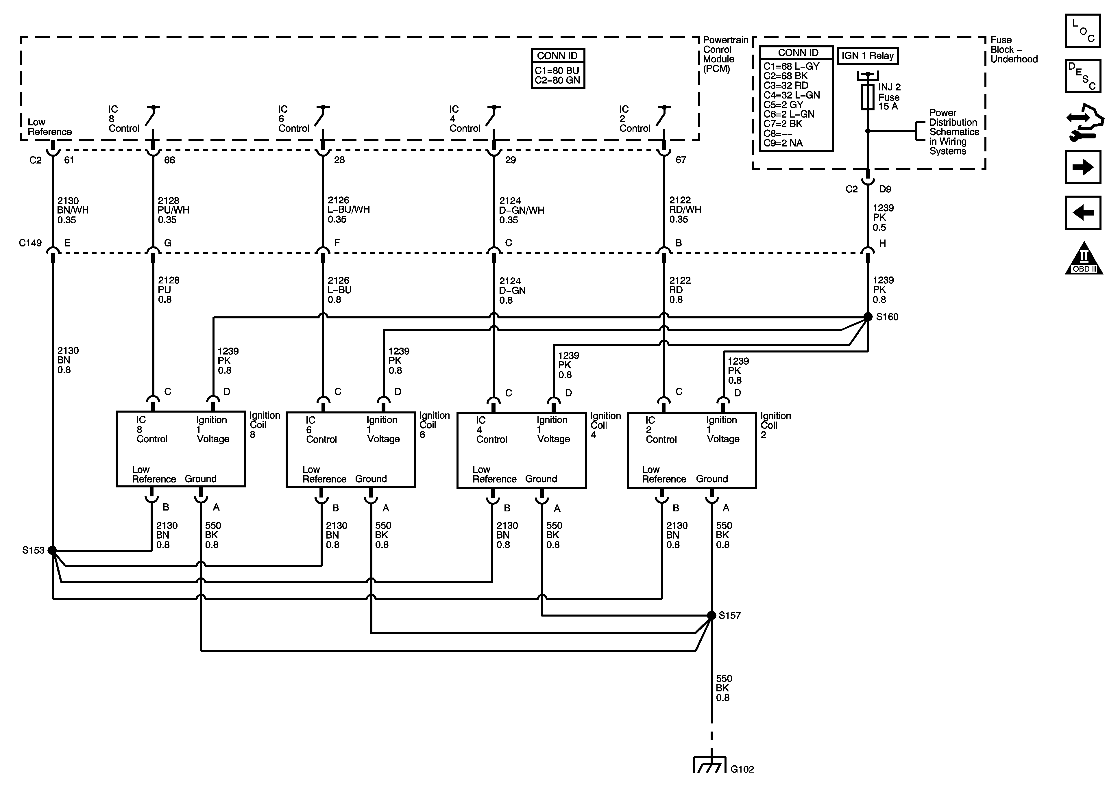
Engine Controls - Ignition System Coils 2, 4, 6, and 8
Engine Data Sensors - Electronic Throttle Control
Engine Controls Schematic Icons
Module Power, Ground, Serial Data, and MIL
INJ 1 and INJ 2 Fuses - 8.1L
G100, G101, and G102
Figure 7:

Ignition Controls - Ignition System Coils 2, 4, 6, and 8


Object Number: 1542627  Size: FS
Master Electrical Component List
Electronic Ignition (EI) System Description
Control Module References
Ignition Controls - Sensors
Engine Controls - Ignition System Coils 1, 3, 5, and 7
Engine Controls Schematic Icons
Module Power, Ground, Serial Data, and MIL
INJ 1 and INJ 2 Fuses - 8.1L
G100, G101, and G102
Figure 8:

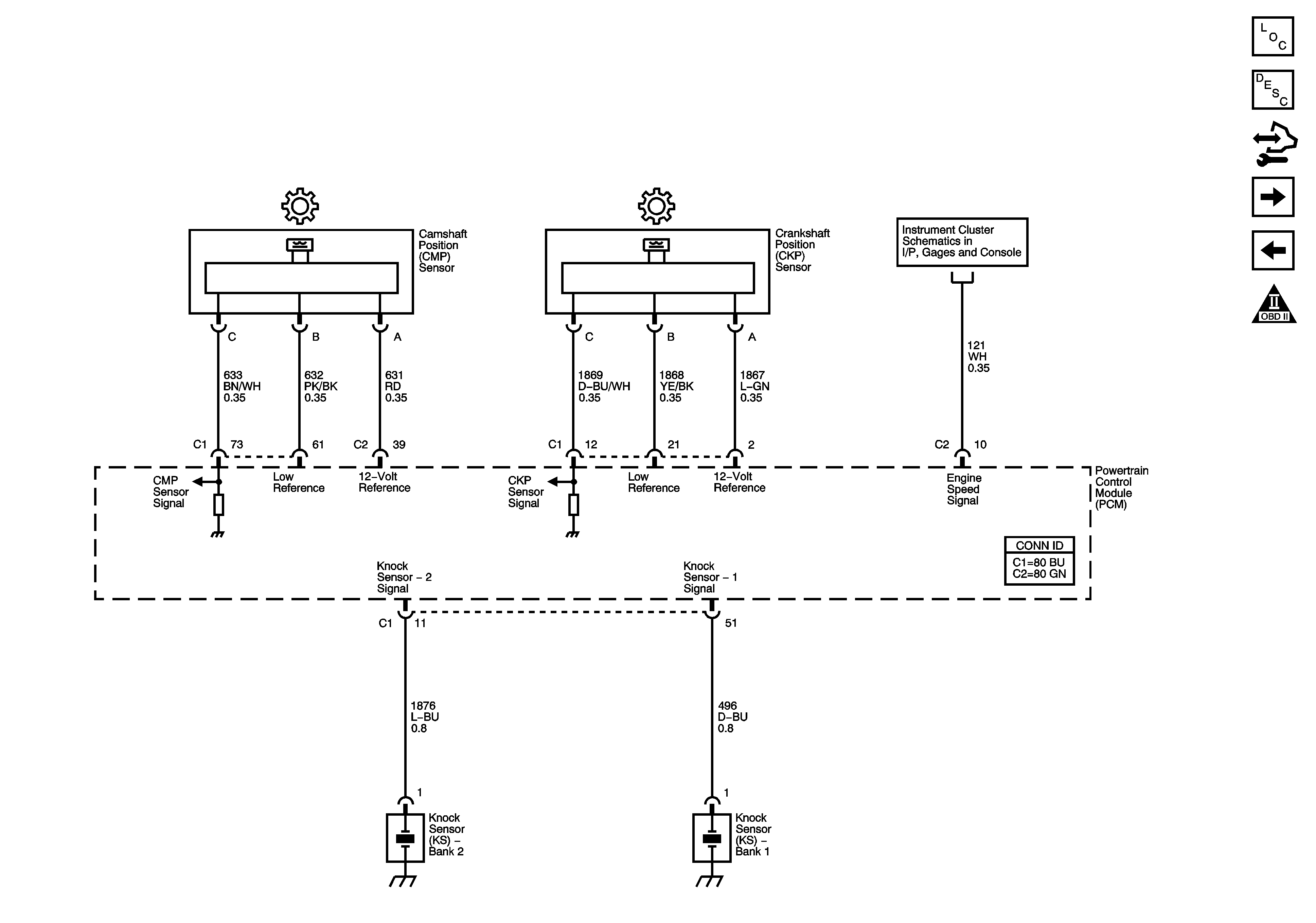
Ignition Controls - Sensors


Object Number: 1542629  Size: FS
Master Electrical Component List
Electronic Ignition (EI) System Description
Control Module References
Fuel Controls - Fuel Pump Controls
Engine Controls - Ignition System Coils 2, 4, 6, and 8
Engine Controls Schematic Icons
Gages, Vehicle Speed Signal, Engine Oil Pressure, and Fuel Level Sensors
Figure 9:

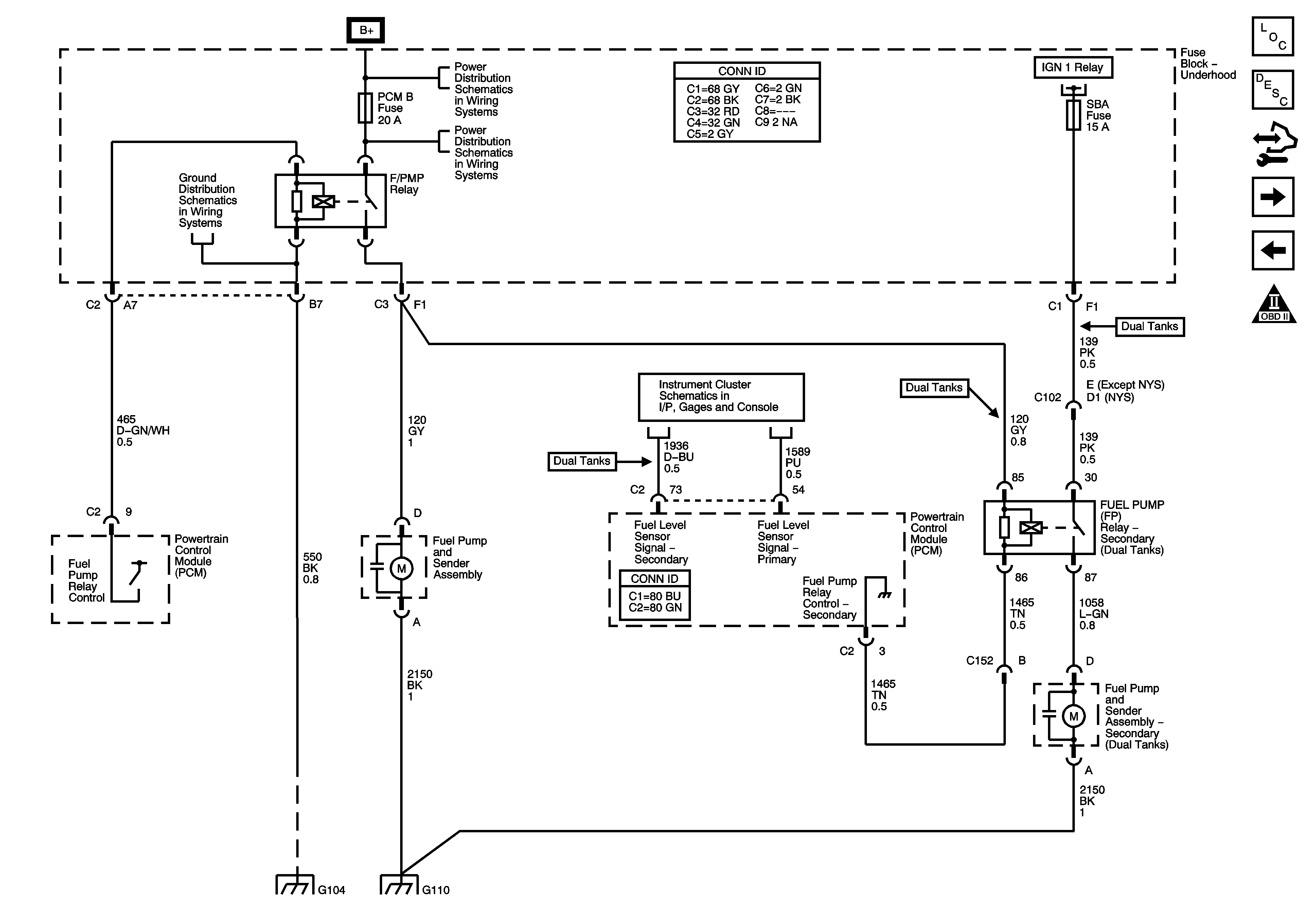
Fuel Controls - Fuel Pump Controls


Object Number: 1553317  Size: FS
Master Electrical Component List
Fuel System Description
Control Module References
Fuel Controls - Fuel Injectors
Ignition Controls - Sensors
Engine Controls Schematic Icons
G104, G106, G107 and G110
B+ Bar Bus
AUX PWR, AUX PWR 2, DDM, ECC, LBEC 2, LOCKS, PCM B, and PDM Fuses
Module Power, Ground, Serial Data, and MIL
Gages, Vehicle Speed Signal, Engine Oil Pressure, and Fuel Level Sensors
G104, G106, G107 and G110
Figure 10:

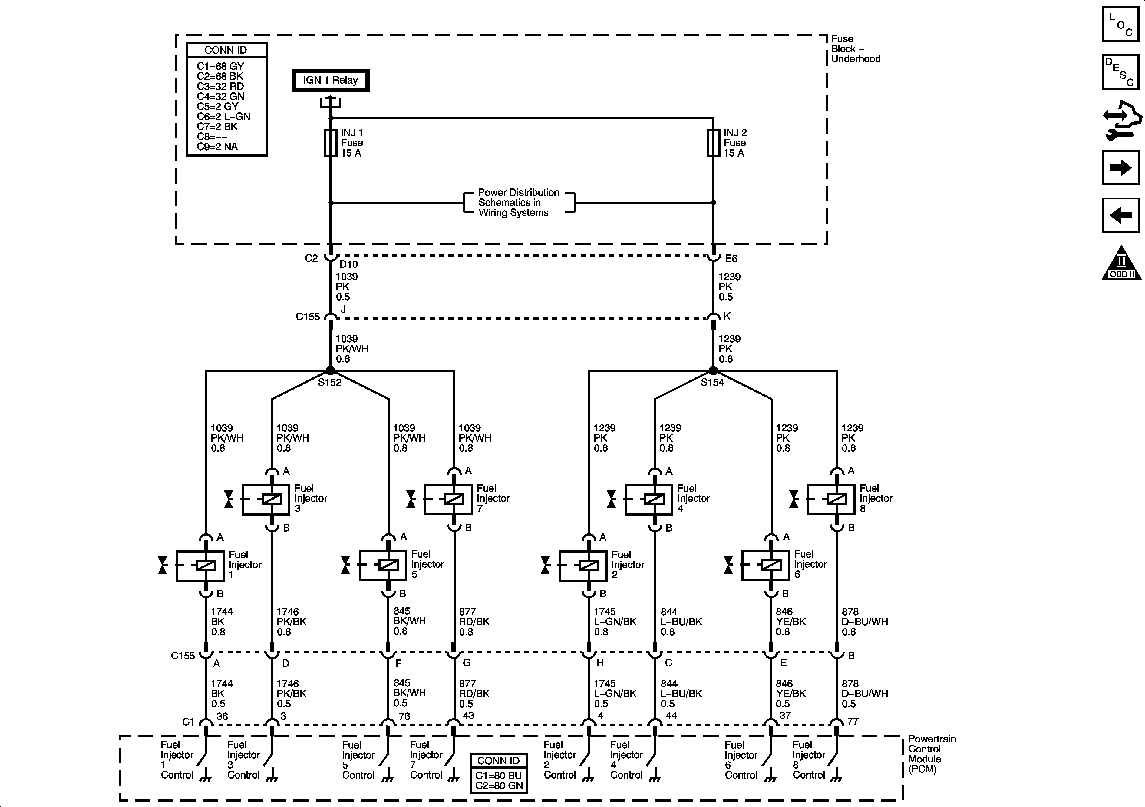
Fuel Controls - Fuel Injectors


Object Number: 1542630  Size: FS
Master Electrical Component List
Fuel System Description
Control Module References
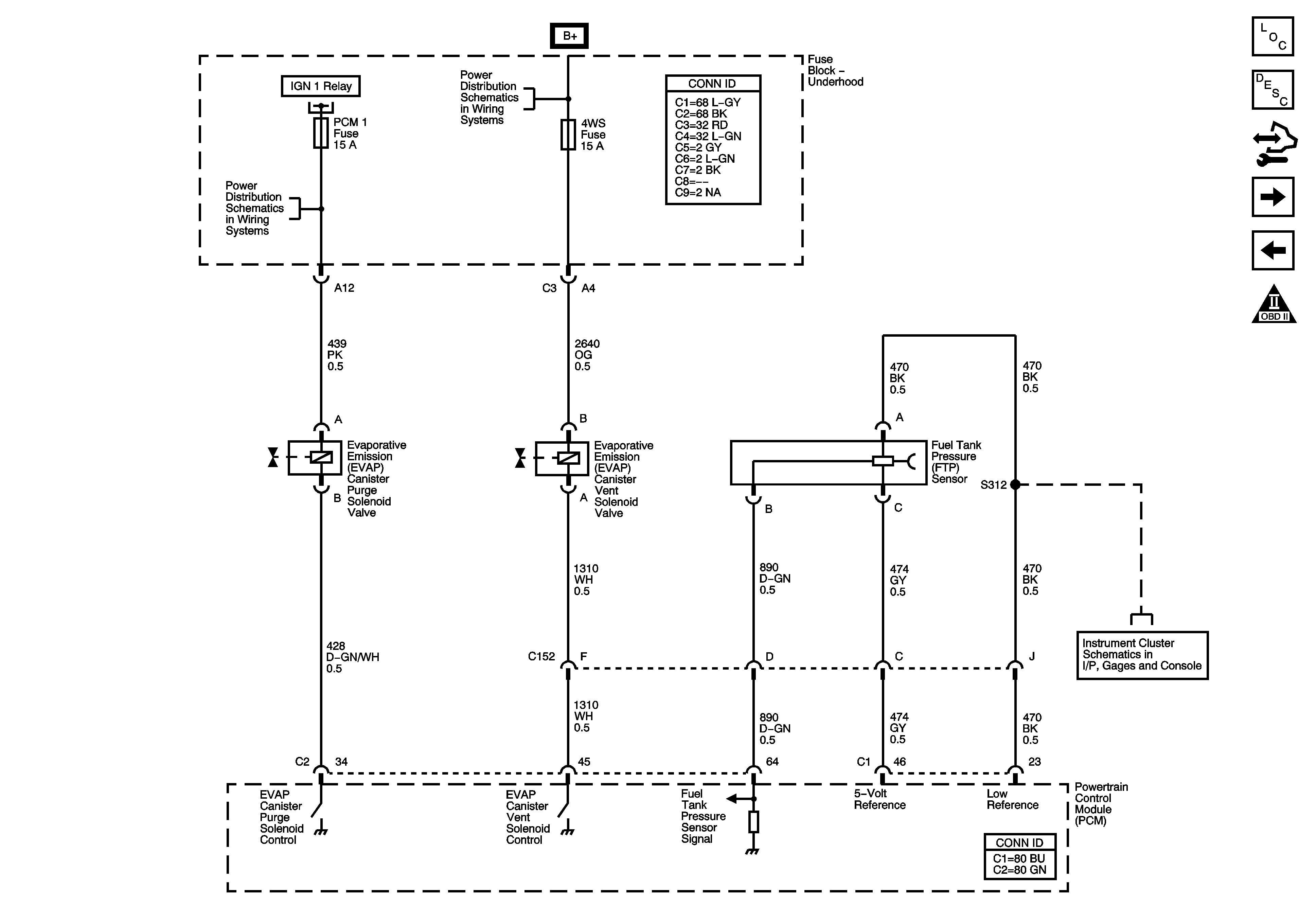
Fuel Controls - EVAP Controls
Fuel Controls - Fuel Pump Controls
Engine Controls Schematic Icons
Module Power, Ground, Serial Data, and MIL
INJ 1 and INJ 2 Fuses - 8.1L
Figure 11:

Fuel Controls - EVAP Controls


Object Number: 1542631  Size: FS
Master Electrical Component List
Evaporative Emission Control System Description
Control Module References
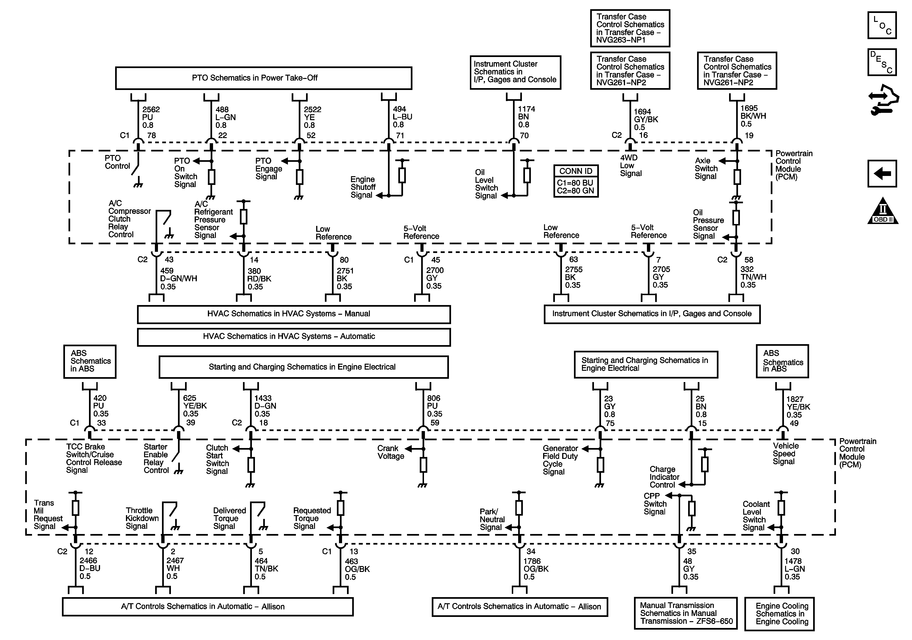
Transmission and Controlled/Monitored Subsystem References
Fuel Controls - Fuel Injectors
Engine Controls Schematic Icons
ETC/ECM, INJ 1, INJ 2, PCM 1, and SBA Fuses - Gas
Module Power, Ground, Serial Data, and MIL
B+ Bar Bus
Gages, Vehicle Speed Signal, Engine Oil Pressure, and Fuel Level Sensors
Figure 12:

Transmission and Controlled/Monitored Subsystem References


Object Number: 1542632  Size: FS
Master Electrical Component List
Powertrain Control Module Description
Control Module References
Fuel Controls - EVAP Controls
Engine Controls Schematic Icons
Power Takeoff
Indicators, Water in Fuel Sensor, Engine Oil Level Switch and Washer Fluid Level Sensor
Power, Ground, Serial Data and Transfer Case Encoder Motor
Transfer Case Control Schematics NP2
A/C Compressor Controls
Gages, Vehicle Speed Signal, Engine Oil Pressure, and Fuel Level Sensors
Power, Ground, Serial Data, Indicator and Stop Lamp Switch - Over 8600 GVW or Rear Drum Brakes
Starting - Gas
Charging - 20/30 Series and HP2
Power, Ground, Serial Data, Indicator and Stop Lamp Switch - Over 8600 GVW or Rear Drum Brakes
MIL Control, Serial Data, Torque Signal and Tow/Haul Switch
Speed Sensors and PNP Switches
Manual Transmission ZF S6-650
8.1L and Diesel