Removal Procedure
- Position the shift lever into the park (P) position.
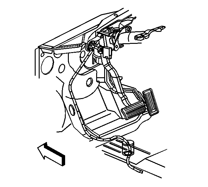
- Remove the instrument panel knee bolster. Refer to Knee Bolster Replacement in Instrument Panel, Gages, and Console.
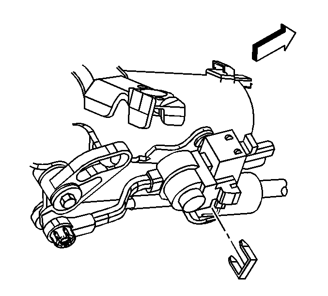
- Remove the retainer securing the cable to the steering column.
- Remove the cable end from the steering column ball stud.
- Depress the tangs and remove the cable from the steering column bracket.
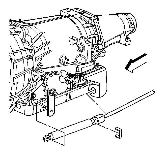
- Remove the bolt securing the cable support to the brace.
- Remove the range selector cable from the support.
- Raise and suitably support the vehicle. Refer to Lifting and Jacking the Vehicle in General Information.
- Ensure the transmission manual shaft is positioned in mechanical park.
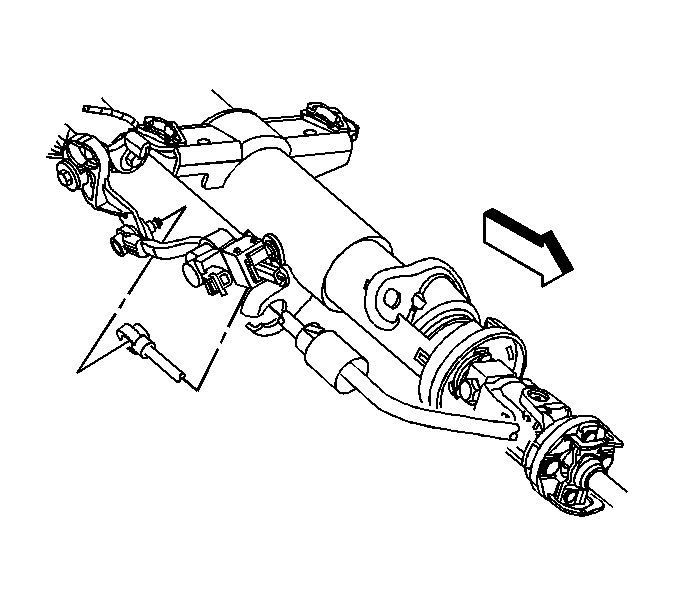
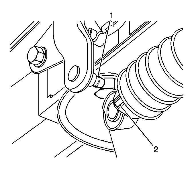
- Remove the range selector cable end (2) from the transmission range selector lever ball stud (1).
- Remove the retainer securing the cable to the bracket.
- Depress the tangs and remove the cable from the transmission bracket.
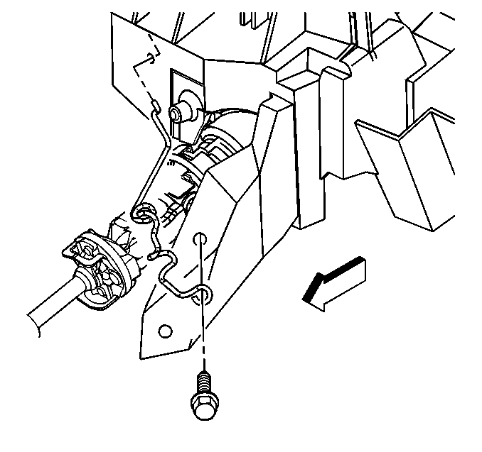
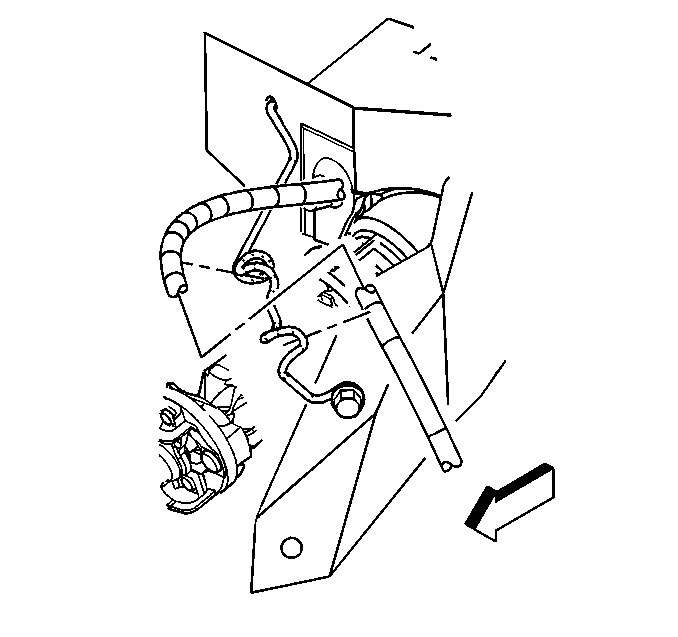
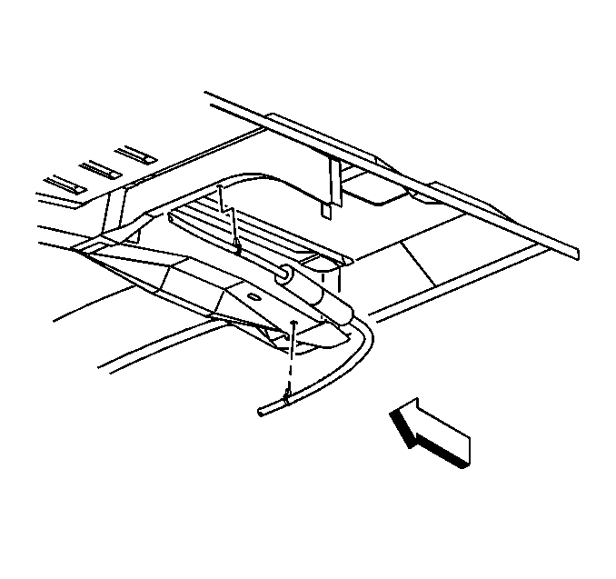
- Remove the cable clips from the floor panel reinforcement.
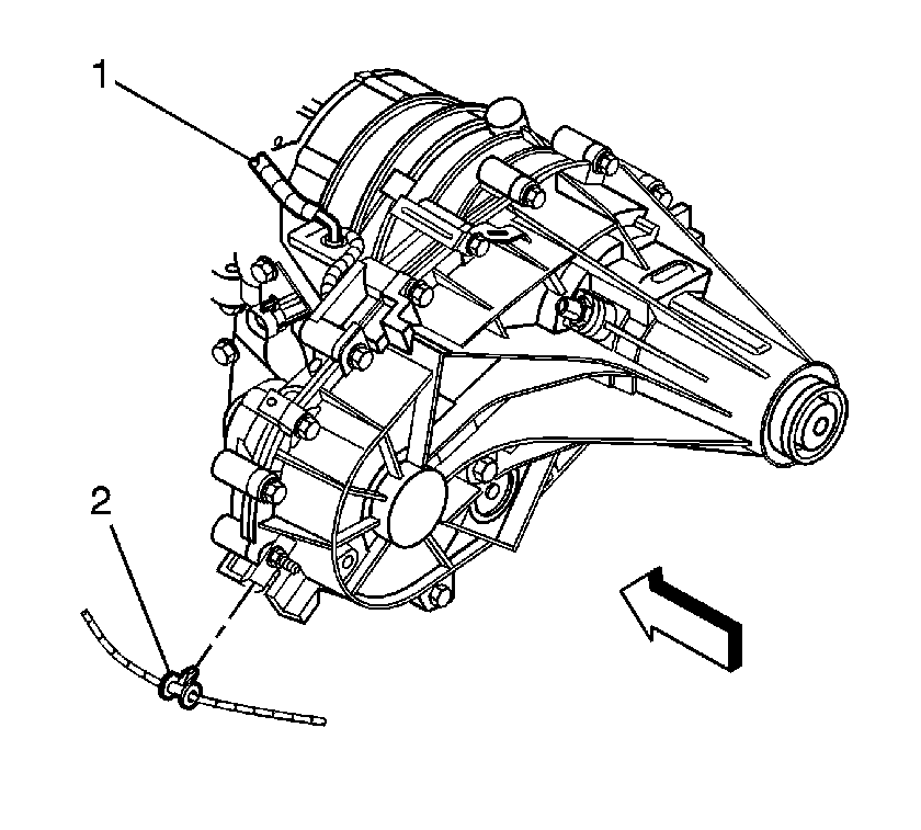
- Remove the cable clips (2) from the transfer case, if equipped.
- Lower the vehicle.
- Pull back the carpet and insulation around the driver's area.
- Remove the cable grommet from the floor panel.
- Remove the cable from the hole in the floor panel.
Important: Avoid unnecessary twisting/bending of the selector cable when removing the cable from the support.
Installation Procedure
- Instal the cable to the hole in the floor panel.
- Install the cable grommet to the floor panel.
- Position the carpet and insulation around the driver's area.
- Raise the vehicle.
- Install the cable clips (2) to the transfer case, if equipped.
- Install the cable clips to the floor panel reinforcement.
- Ensure the transmission manual shaft is positioned in mechanical park.
- Install the cable to the transmission bracket.
- Install the retainer securing the cable to the bracket.
- Install the range selector cable end (2) to the transmission range selector lever ball stud (1).
- Lower the vehicle.
- Install the range selector cable to the support.
- Install the bolt securing the cable support to the brace.
- Install the cable to the steering column bracket.
- Install the cable end to the steering column ball stud.
- Install the retainer securing the cable to the steering column.
- Install the instrument panel knee bolster. Refer to Knee Bolster Replacement in Instrument Panel, Gages, and Console.
- If all of the gear positions cannot be achieved, adjust the cable. Refer to Range Selector Lever Cable Adjustment .
Important: Avoid unnecessary twisting/bending of the range selector cable when removing the cable from the support.
Notice: Use the correct fastener in the correct location. Replacement fasteners must be the correct part number for that application. Fasteners requiring replacement or fasteners requiring the use of thread locking compound or sealant are identified in the service procedure. Do not use paints, lubricants, or corrosion inhibitors on fasteners or fastener joint surfaces unless specified. These coatings affect fastener torque and joint clamping force and may damage the fastener. Use the correct tightening sequence and specifications when installing fasteners in order to avoid damage to parts and systems.
Tighten
Tighten the bolt to 10 N·m (89 lb in).
