Special Tools
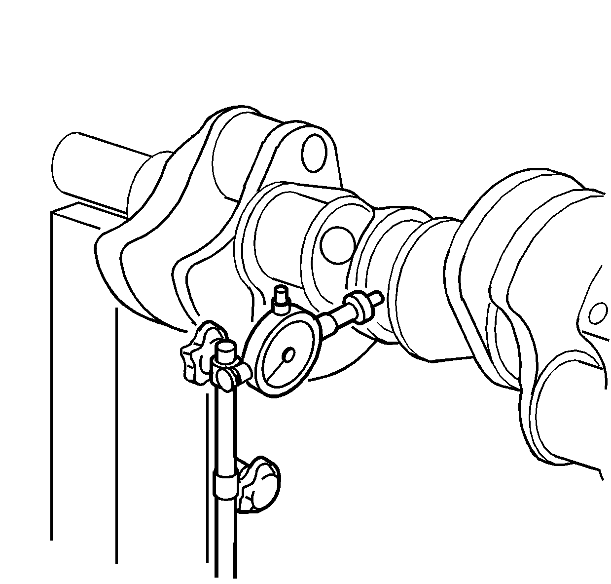
- Clean the crankshaft and bearings.
- Inspect the crankshaft for the following conditions.
| • | Excessive wear or damage on the surface of the crankshaft journals. |
| • | Excessive wear or damage to the crankshaft gear. |
| • | Excessive wear or damage on the oil seal fitting surface. |
| • | Inspect the oil ports for obstructions. |
| • | Replace the crankshaft if there is excessive wear or damage to the journals, oil seal fitting surface or to the crankshaft gear. |
- Measure the crankshaft run out.
| 3.1. | Mount the crankshaft in wooden V-blocks. |
| 3.2. | Set
J 7872
on the center of the crankshaft journal. |
| 3.3. | Turn the crankshaft in the normal direction of rotation. |
| 3.4. | Record readings. The production value is 0.05 mm (0.0020 in) and the service limit is 0.44 mm (0.0173 in). |
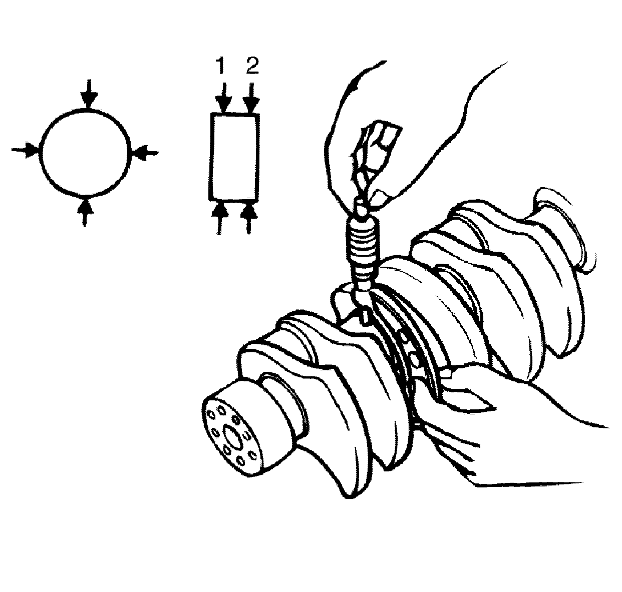
- Measure the crankshaft journal diameter across four points.
| • | The crankshaft journal outside diameter is 79.905-79.925 mm (3.1459-3.1466 in) and the service limit is 79.89 mm (3.1453 in). |
| • | Replace the crankshaft if the measured value is less than the service limit. |
- Measure the crankpin outside diameter across four points.
| • | The crankpin outside diameter is 62.902-62.922 mm (2.4765-2.4772 in) and the service limit is 62.88 mm (2.4756 in). |
| • | Replace the crankshaft if the measured value is less than the service limit. |
Crankshaft Bearing Selection
There are two methods for selecting the proper size crankshaft bearings. The first one is to select the bearing grade (color code) based on the cylinder block grade and the crankshaft journal grade from the Crankshaft Bearing Grade chart. The second is
the plastic gauge method.
Crankshaft Bearing Selection Grade Chart Method
Stamp ID
| Main Journal
| Conn. Rod Journal
|
No Stamp
| STD
| STD
|
M20 R20
| 0.020 in
| 0.020 in
|
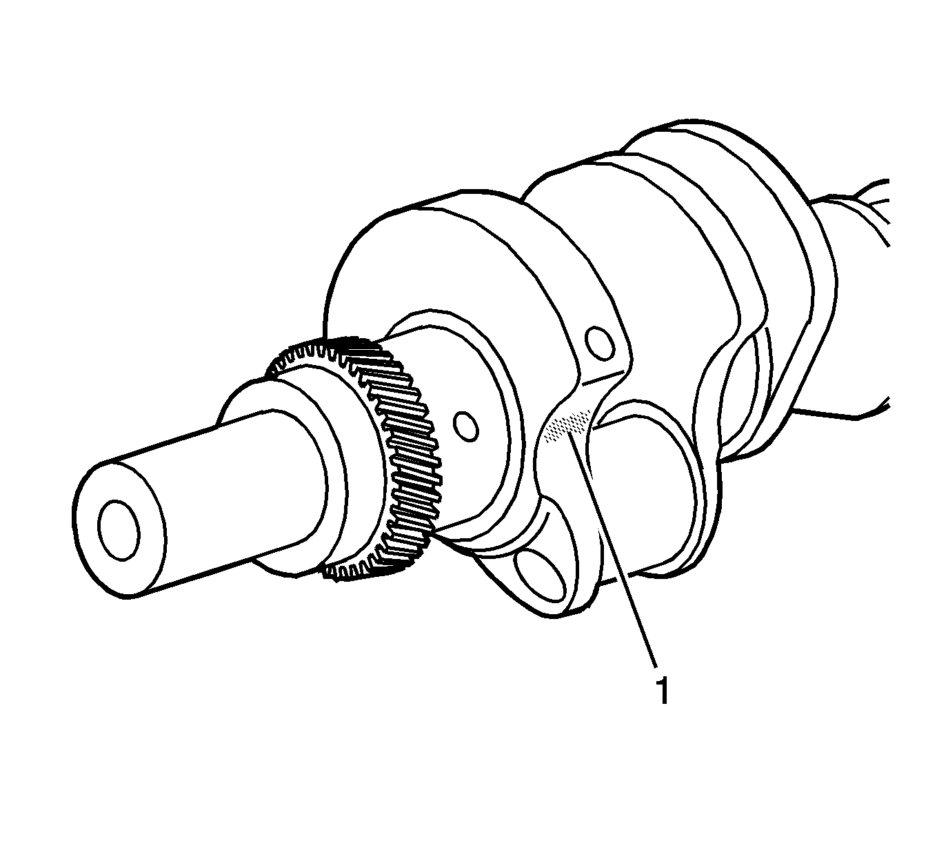
Important: All crankshafts that have been machined have a steel stamping (1) on the 1st counterweight.
- Inspect the crankshaft for stamping (1) indicating undersized main and/or rod journals.
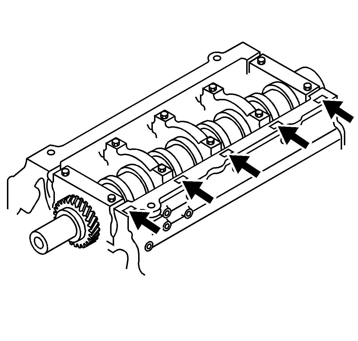
- The cylinder block grade is indicated on the right lower portion of the cylinder block.
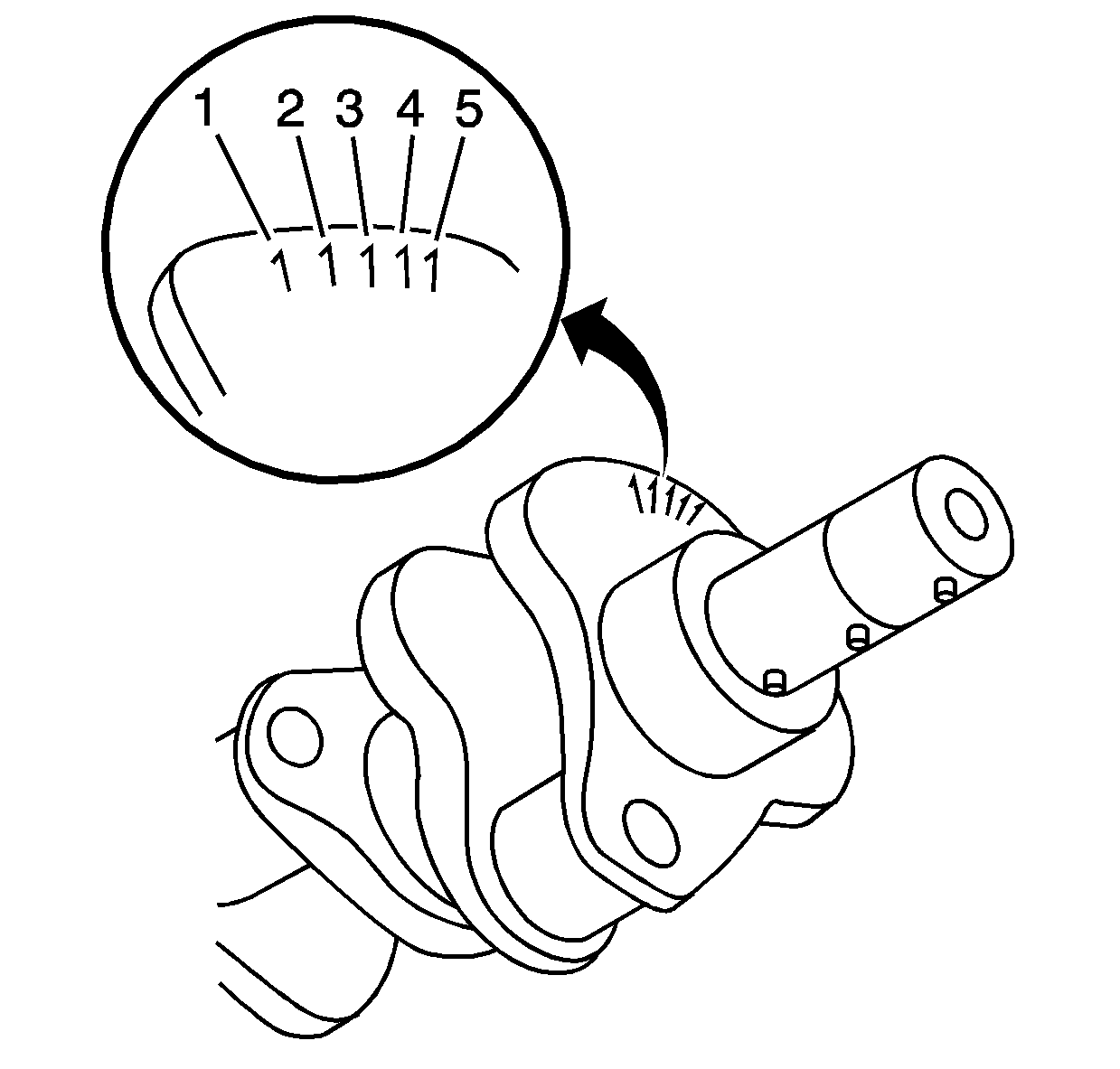
- The crankshaft journal grade is indicated on the number 1 crankshaft counterweight.
- Match the cylinder block grade and the crankshaft journal grade, refer to
Crankshaft Bearing Selection Specifications
.
- From the Crankshaft Bearing Grade chart, determine which bearing grade (color code) is required.
- Verify the crankshaft bearing clearance using the plastic gage method.
Crankshaft Bearing Selection Plastic Gage Method
Special Tools
J 45059
Angle Meter
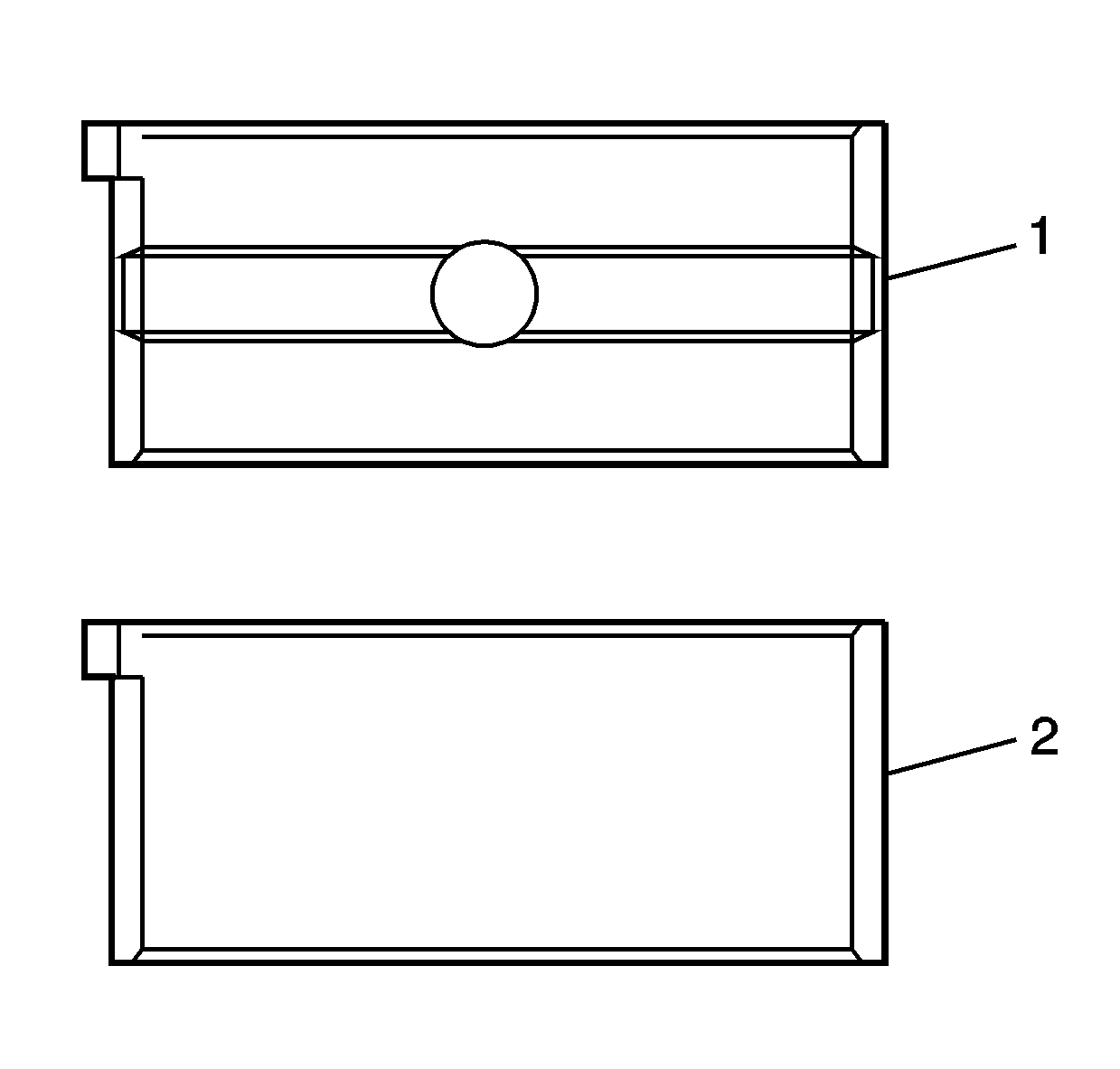
- Clean the cylinder block bearing fitting surfaces.
- Clean the crankshaft and upper bearings (1) and lower bearings (2).
- Install the bearings into the cylinder block and the bearing caps.
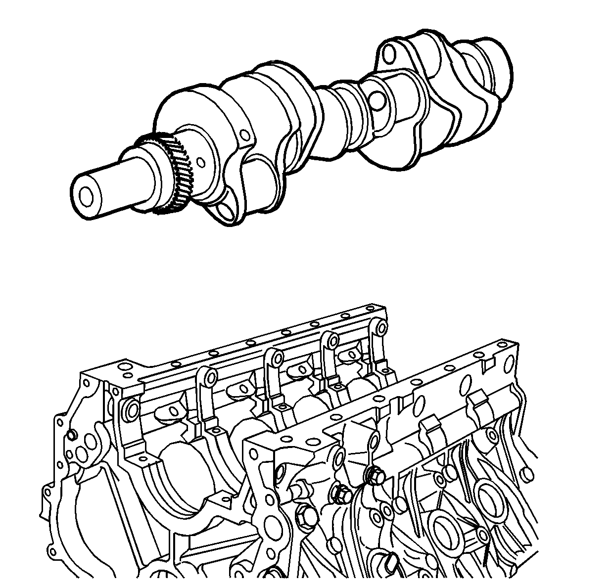
- Install the crankshaft into the cylinder block.
- Rotate the crankshaft approximately 30 degrees to seat the bearings.
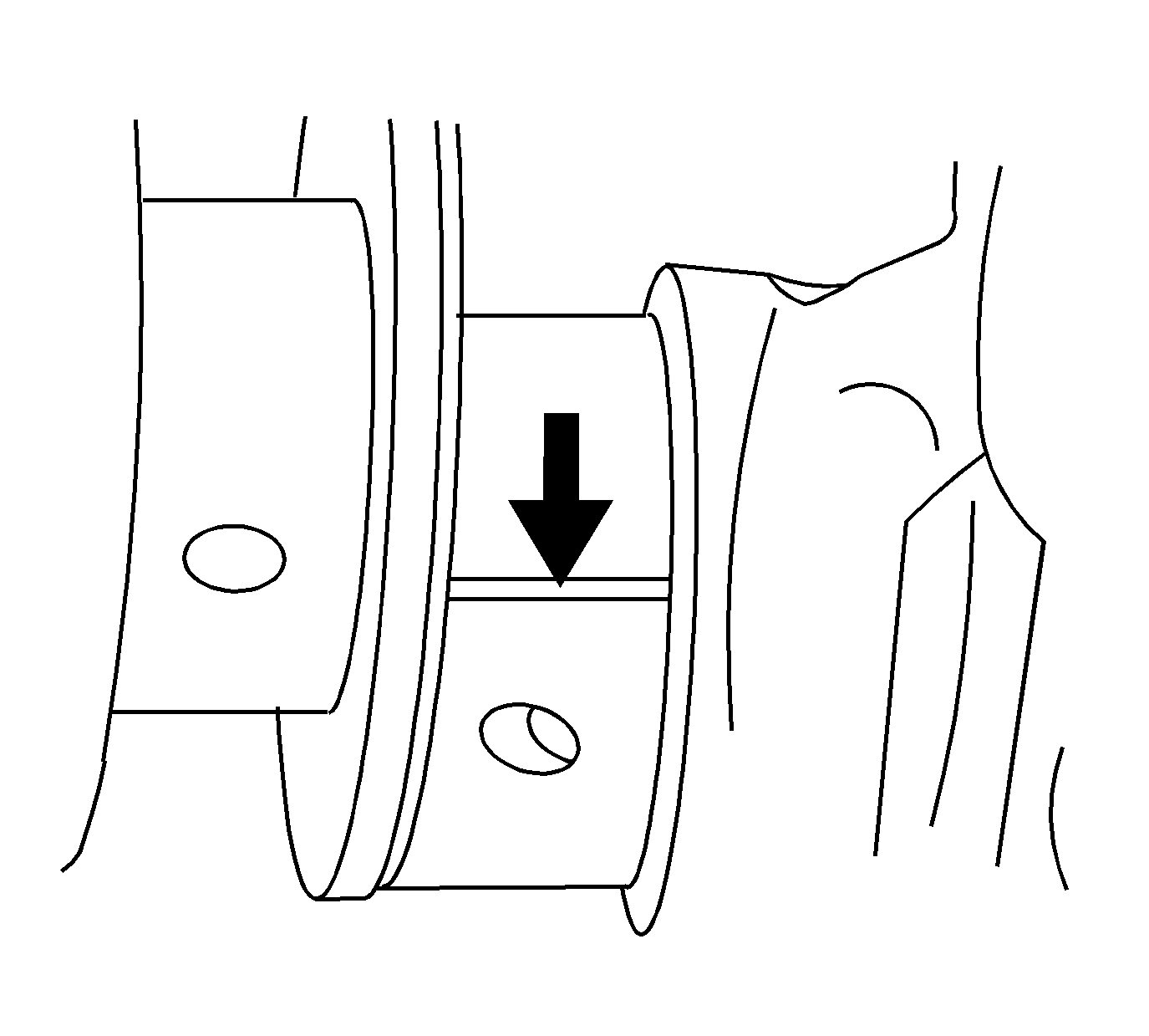
Important: Do not allow the crankshaft to rotate at any time during bearing cap installation and tightening or the plastic gauge measurement will be inaccurate.
- Place the plastic gage over the crankshaft journal across the full width of the bearing.
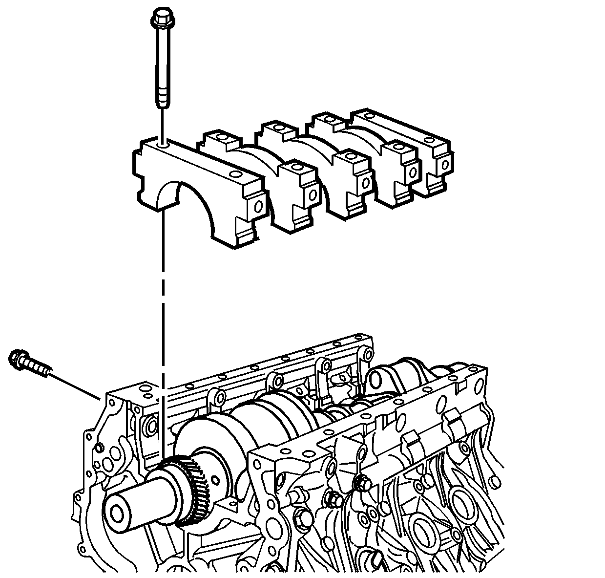
- Install the crankshaft bearing caps.
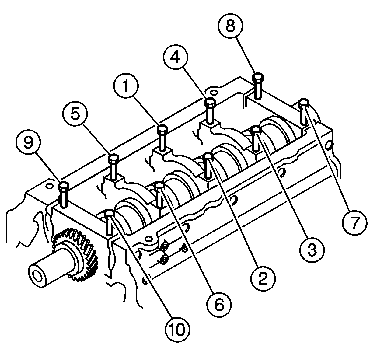
Notice: Use the correct fastener in the correct location. Replacement fasteners
must be the correct part number for that application. Fasteners requiring
replacement or fasteners requiring the use of thread locking compound or sealant
are identified in the service procedure. Do not use paints, lubricants, or
corrosion inhibitors on fasteners or fastener joint surfaces unless specified.
These coatings affect fastener torque and joint clamping force and may damage
the fastener. Use the correct tightening sequence and specifications when
installing fasteners in order to avoid damage to parts and systems.
- Install the crankshaft bearing cap bolts.
- Tighten the crankshaft bearing cap bolts in the proper sequence.
Tighten
| • | 1st step 98 N·m (72 lb ft). |
| • | 2nd step 132 N·m (97 lb ft). |
| • | 3rd step 30 degrees using
J 45059
. |
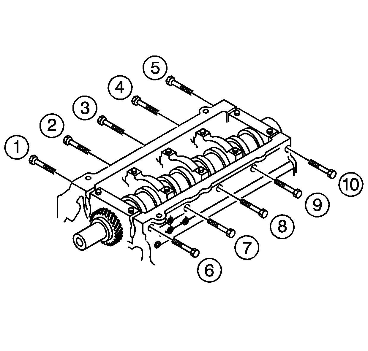
- Install the crankshaft bearing cap side bolts.
Tighten
Tighten the crankshaft bearing cap side bolts in the proper sequence to 70 N·m (52 lb ft).
- Remove the crankshaft bearing cap bolts.
- Remove the crankshaft bearing caps.
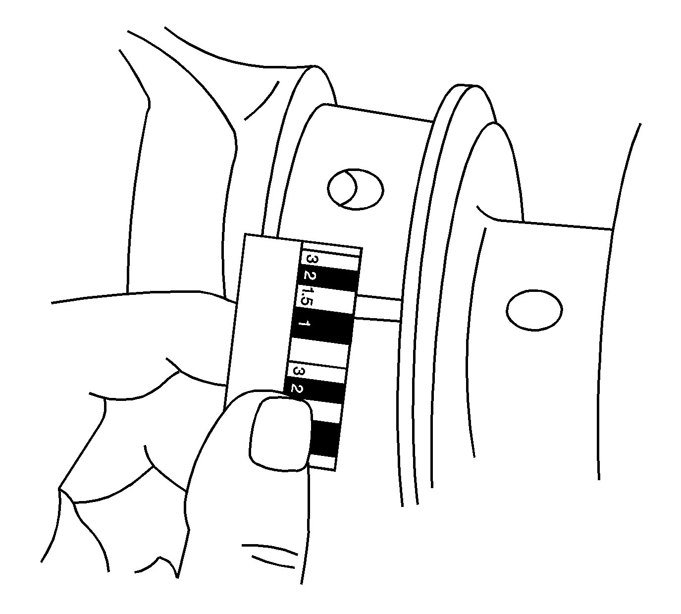
- Compare the width of the plastic gauge with the scale printed on the plastic gauge
container.
- Select the crankshaft bearing grade that provides the proper oil clearances. The production specification for crankshaft bearing clearance is 0.039-0.070 mm (0.0015-0.0028 in) and the service limit is 0.014 mm (0.0055 in).


