Service of the powertrain control module (PCM) should consist of either replacement of the PCM or programming of the electrically erasable programmable read only memory (EEPROM). If the diagnostic procedures call for the PCM to be replaced, the replacement PCM should be checked to ensure that the correct part is being used. If the correct part is being used, remove the faulty PCM and install the new service PCM.
Removal Procedure
Important:
• To prevent internal PCM damage, the ignition switch must be OFF when disconnecting
or connecting power to the PCM. • Remove any debris from around the PCM connector surfaces before servicing
the PCM. Inspect the PCM module connector gaskets when diagnosing or replacing
the PCM. Ensure that the gaskets are installed correctly. The gaskets prevent contaminant
intrusion into the PCM. • The replacement PCM must be programmed.
- Using a scan tool, retrieve the percentage of remaining engine oil. Record the remaining engine oil life.
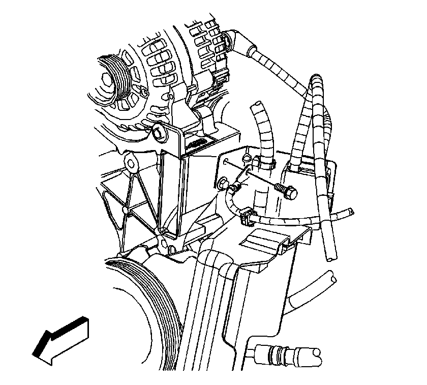
- Disconnect the negative battery cable. Refer to Battery Negative Cable Disconnection and Connection in Engine Electrical.
- If equipped with regular production option (RPO) NYS, remove the harness ground clip from the PCM cover.
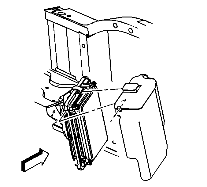
- Release the PCM cover mounting tabs.
- Release the PCM cover from the mounting bracket.
- Remove the PCM cover.
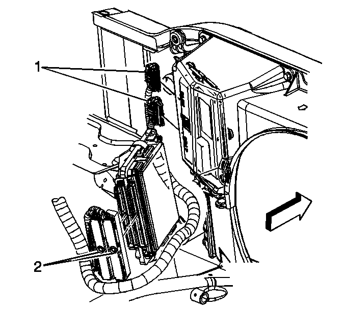
- Loosen the PCM electrical connector bolts (2).
- Disconnect the PCM electrical connectors.
- Release the spring latch from the PCM.
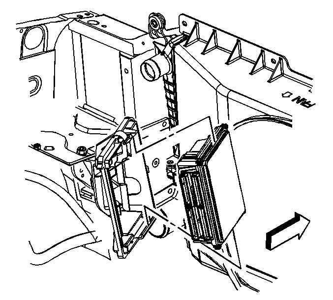
- Release the PCM mounting tabs from the PCM.
- Remove the PCM.
Important: It is necessary to record the remaining engine oil life. If the replacement module is not programed with the remaining engine oil life, the engine oil life will default to 100%. If the replacement module is not programmed with the remaining engine oil life, the engine oil will need to be changed at 5000 km (3,000 mi) from the last engine oil change.
Notice: Do not touch the connector pins or soldered components on the circuit board in order to prevent possible electrostatic discharge (ESD) damage to the PCM.
Notice: In order to prevent internal damage to the PCM, the ignition must be OFF when disconnecting or reconnecting the PCM connector.
Installation Procedure
- Install the PCM.
- Secure the spring latch to the PCM.
- Connect the PCM electrical connectors.
- Tighten the PCM electrical connector bolts (2).
- Install the PCM cover.
- If equipped with RPO NYS, install the harness ground clip to the PCM cover.
- Connect the negative battery cable. Refer to Battery Negative Cable Disconnection and Connection in Engine Electrical.
- If a NEW PCM was installed, program the PCM. Refer to Service Programming System (SPS) in Programming.
- Perform the crankshaft position (CKP) system variation learn procedure. Refer to Crankshaft Position System Variation Learn .
Ensure that the mounting tabs are engaged.
Notice: Use the correct fastener in the correct location. Replacement fasteners must be the correct part number for that application. Fasteners requiring replacement or fasteners requiring the use of thread locking compound or sealant are identified in the service procedure. Do not use paints, lubricants, or corrosion inhibitors on fasteners or fastener joint surfaces unless specified. These coatings affect fastener torque and joint clamping force and may damage the fastener. Use the correct tightening sequence and specifications when installing fasteners in order to avoid damage to parts and systems.
Tighten
Tighten the bolts to 8 N·m (71 lb in).
