Tools Required
J 29714-A Servo Cover Depressor
Removal Procedure
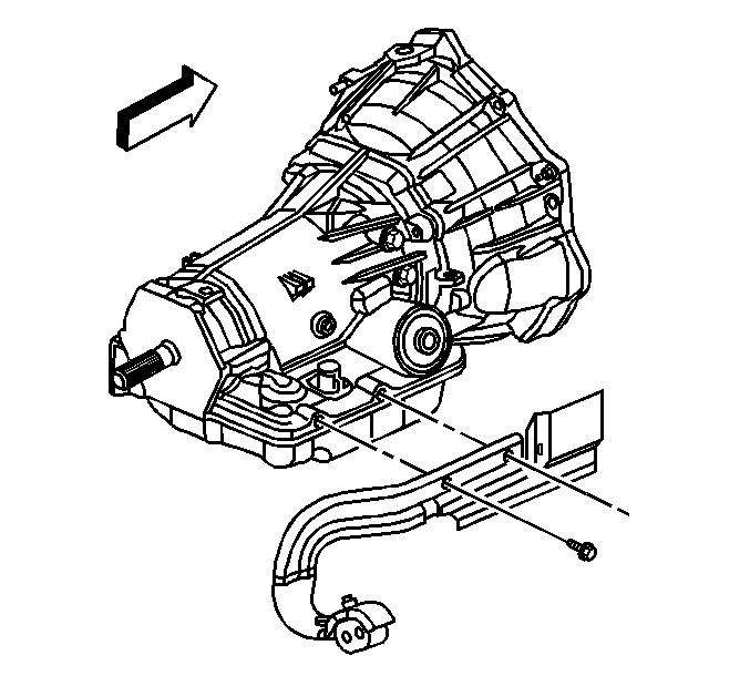
- Remove the exhaust pipe. Refer to Exhaust Manifold Pipe Replacement .
- Remove the heat shield bolts.
- Remove the heat shield.
- Remove the oil pan bolt below the servo.
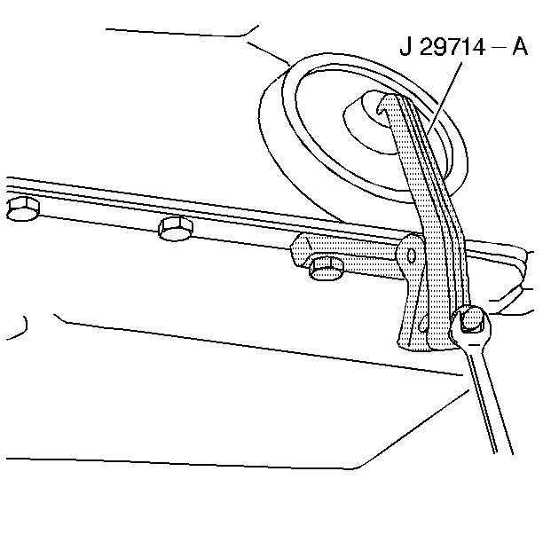
- Install the J 29714-A .
- Tighten the bolt on J 29714-A in order to compress the servo cover.
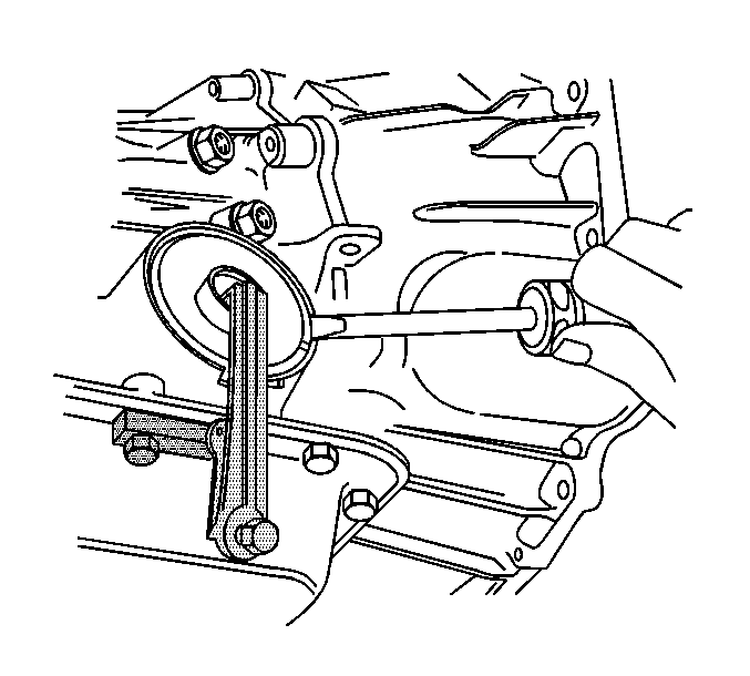
- Remove the servo cover ring.
- Remove the J 29714-A .
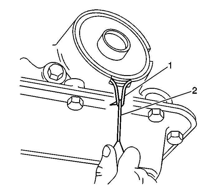
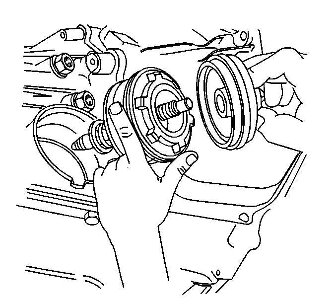
- Remove the servo cover and O-ring seal. If the cover is hung up on the seal, use a pick (2) in order to pull and stretch the seal (1) out of the groove. Cut and remove the O-ring seal before removing the cover.
- Remove the 2-4 servo.
- Inspect the 4th apply piston, 2-4 servo converter, 2nd apply piston, and the servo piston inner housing for the following defects:
| • | Cracks |
| • | Scoring |
| • | Burrs and nicks |
Installation Procedure
- Install NEW seals onto the servo pistons and the servo cover.
- Install the 2-4 servo.
- Install the J 29714-A .
- Tighten the bolt on J 29714-A in order to compress the servo cover.
- Install the servo cover ring.
- Remove the J 29714-A .
- Install the oil pan bolt.
- Install the heat shield and bolts.
- Install the exhaust pipe. Refer to Exhaust Manifold Pipe Replacement .
- Fill the transmission to the proper level with DEXRON® VI transmission fluid. Refer to Transmission Fluid Check .
- Reset the TAP values. Refer to Transmission Adaptive Functions .


Notice: Use the correct fastener in the correct location. Replacement fasteners must be the correct part number for that application. Fasteners requiring replacement or fasteners requiring the use of thread locking compound or sealant are identified in the service procedure. Do not use paints, lubricants, or corrosion inhibitors on fasteners or fastener joint surfaces unless specified. These coatings affect fastener torque and joint clamping force and may damage the fastener. Use the correct tightening sequence and specifications when installing fasteners in order to avoid damage to parts and systems.
Tighten
Tighten the bolt to 11 N·m (97 lb in).

Tighten
Tighten the bolts to 17 N·m (13 lb ft).
Important: It is recommended that transmission adaptive pressure (TAP) information be reset.
Resetting the TAP values using a scan tool will erase all learned values in all cells. As a result, The ECM, PCM or TCM will need to relearn TAP values. Transmission performance may be affected as new TAP values are learned.