Tools Required
J 36660-A Torque Angle Meter
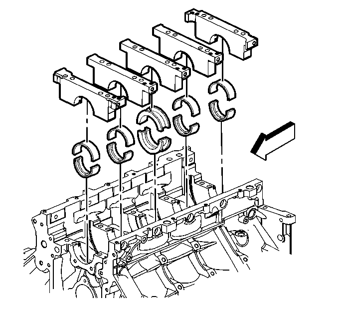
- Install the crankshaft thrust bearings to the engine block and center bearing caps.
- Install the remaining crankshaft bearings to the engine block and bearing caps.
- Lubricate the bearing surfaces and crankshaft journals with clean engine oil.
- Install the crankshaft.
- Install the crankshaft bearing caps, with bearings, into the engine block.
- Start the M10 bolts and bolt/studs.
- Tap the bearing caps into place with a plastic-faced hammer.
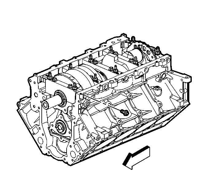
- Install the NEW M8 bearing cap side bolts.
- Tighten the bearing cap bolts and studs.
- Using a plastic face hammer, tap the crankshaft rearward then forward in order to align the thrust bearings.
- Tighten the inner M10 bolts final pass in sequence 80 degrees using the J 36660-A .
- Tighten the outer M10 bolts/studs first pass in sequence to 20 N·m (15 lb ft).
- Tighten the outer M10 bolts/studs final pass in sequence 51 degrees using the J 36660-A .
- Tighten the bearing cap side M8 bolts to 25 N·m (18 lb ft).
- Install the crankshaft position sensor.
- Measure the crankshaft end play.
Important:
• Crankshaft bearing clearances are critical. Excessive crankshaft bearing clearance may affect crankshaft position (CKP) sensor signals and/or on-board diagnostics (OBD) II system performance. • Crankshaft bearing caps must be installed to the proper location and direction. • When installing the crankshaft bearings, align the locating tabs on the bearings with the locating notches in the engine block journal bore and the bearing cap. • Always install crankshaft bearings with their machined partner. Do not file bearings or mix bearing halves. • In order to prevent engine block oil leakage, install NEW M8 crankshaft bearing cap side bolts. The crankshaft bearing cap M8 side bolts have a pre-applied sealant patch applied to the bolt flange.
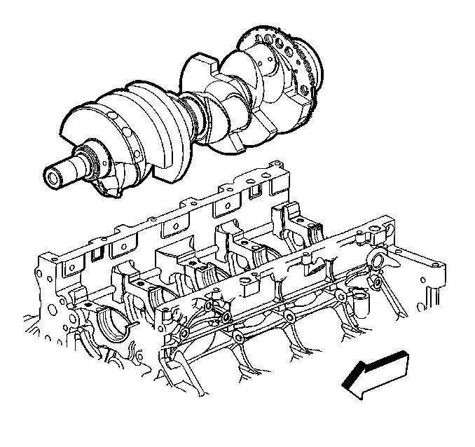
Notice: To maintain proper crankshaft end play, use extreme care during crankshaft installation. Avoid scoring or damaging the thrust bearing.
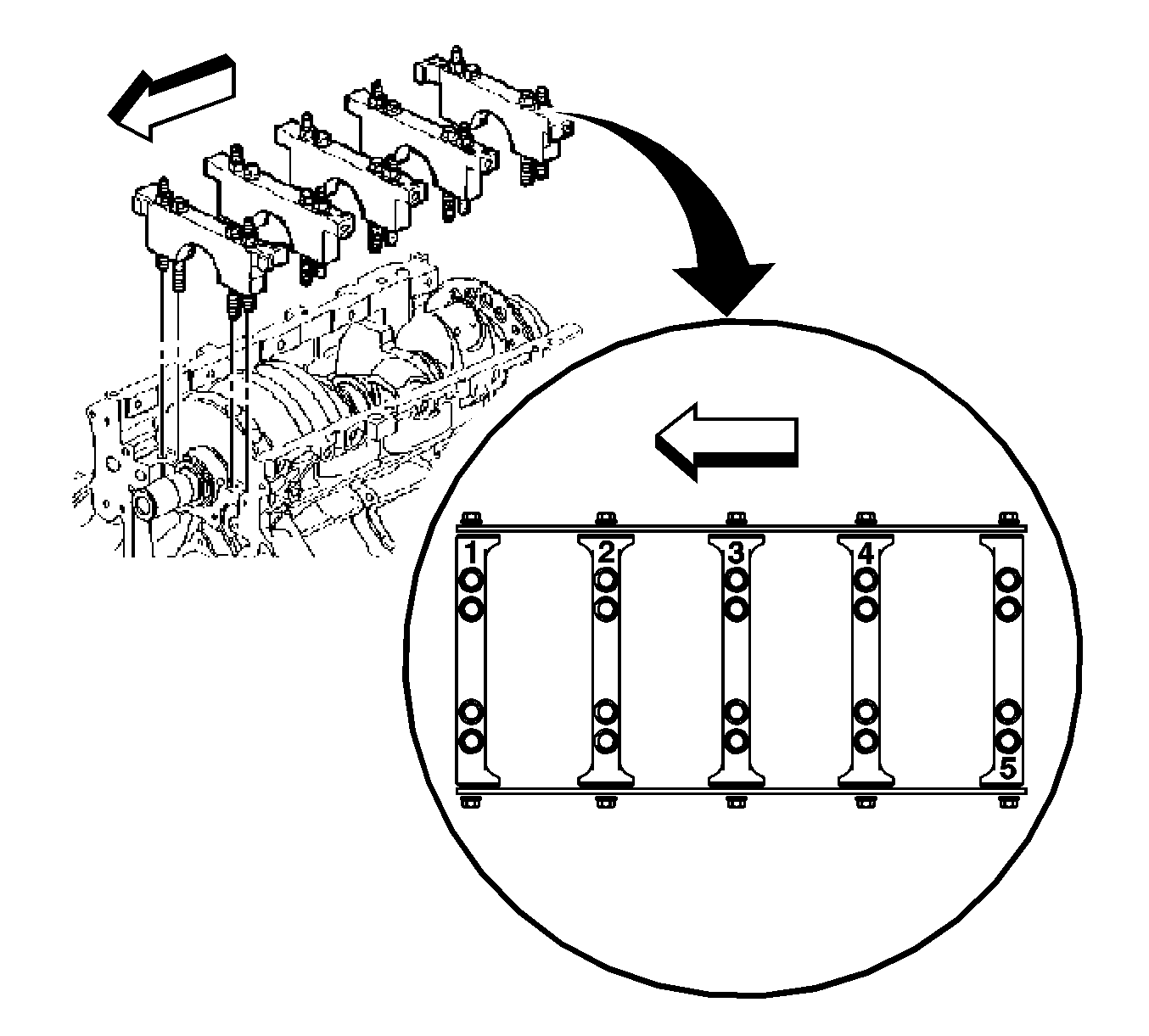
Important: The bearing caps must be installed in the proper location and direction.
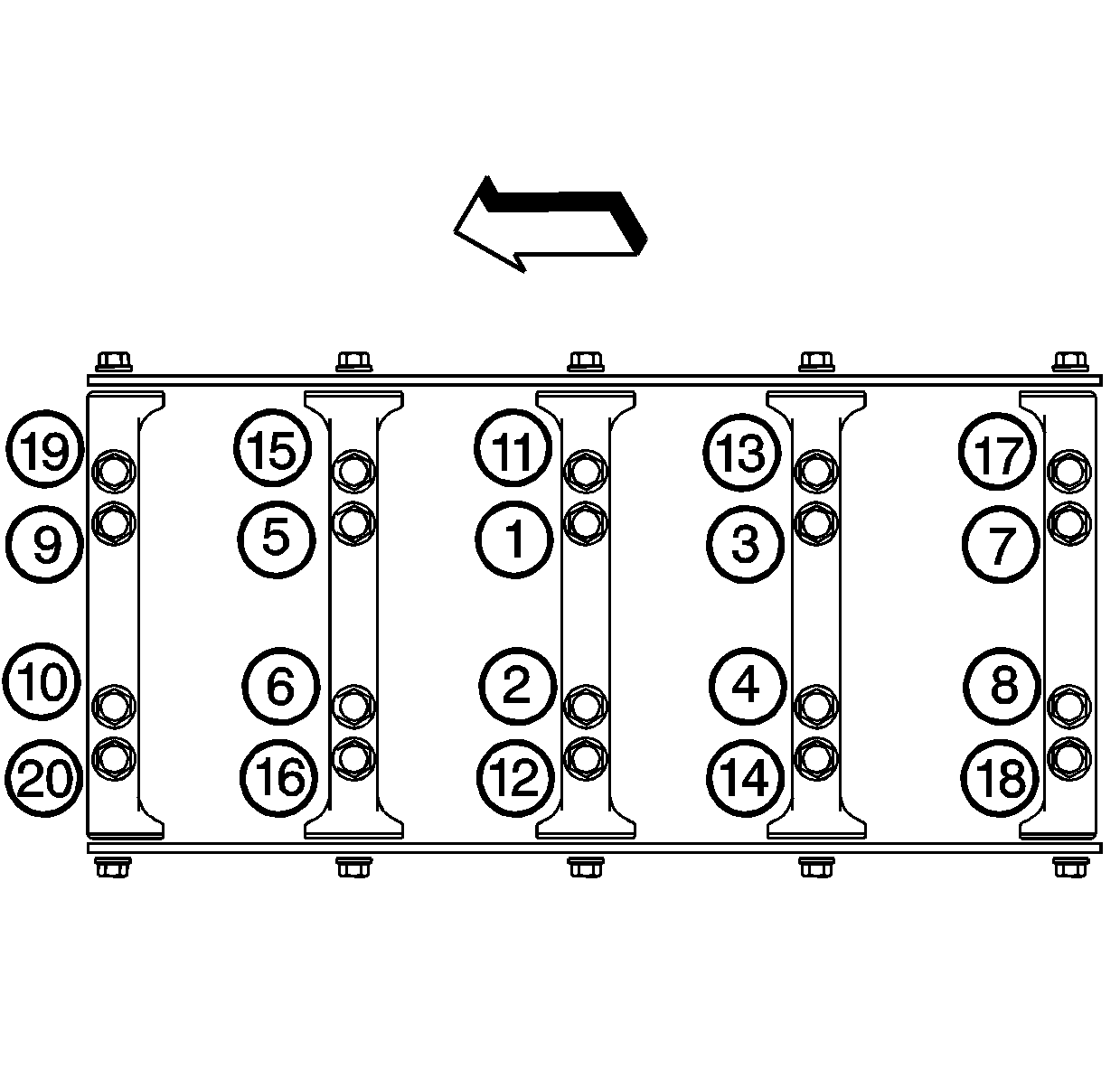
Notice: Use the correct fastener in the correct location. Replacement fasteners must be the correct part number for that application. Fasteners requiring replacement or fasteners requiring the use of thread locking compound or sealant are identified in the service procedure. Do not use paints, lubricants, or corrosion inhibitors on fasteners or fastener joint surfaces unless specified. These coatings affect fastener torque and joint clamping force and may damage the fastener. Use the correct tightening sequence and specifications when installing fasteners in order to avoid damage to parts and systems.
Tighten
Tighten the inner M10 bearing cap bolts first pass in sequence to 20 N·m (15 lb ft).
Important: To properly align the crankshaft thrust bearings, the final thrust of the crankshaft MUST be in the forward direction.
Tighten
Tighten the bolt on one side of the bearing cap and then tighten the bolt on the opposite side of the same bearing cap.
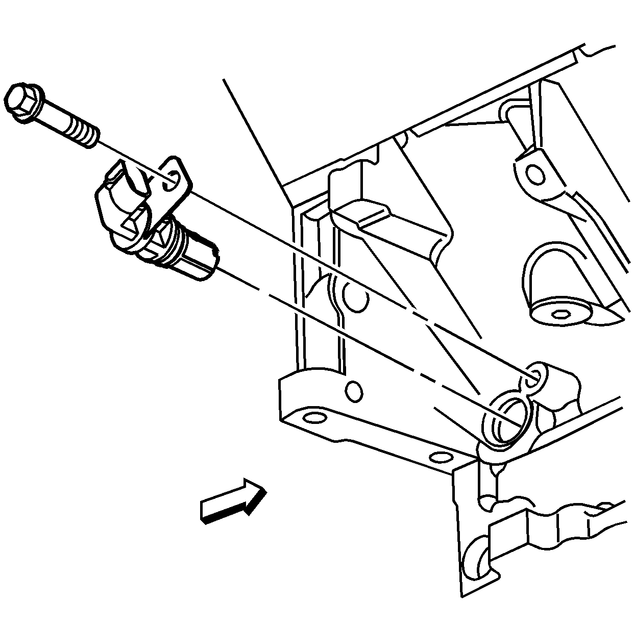
| 11.1. | Inspect the crankshaft position sensor O-ring seal. If the O-ring seal is not cut or damaged, it may be used. |
| 11.2. | Coat the O-ring seal with clean engine oil. |
| 11.3. | Install the sensor. Align the notch in the sensor retaining bracket with the bolt hole in the block. |
| 11.4. | Install the sensor bolt. |
Tighten
Tighten the crankshaft position sensor bolt to 25 N·m (18 lb ft).
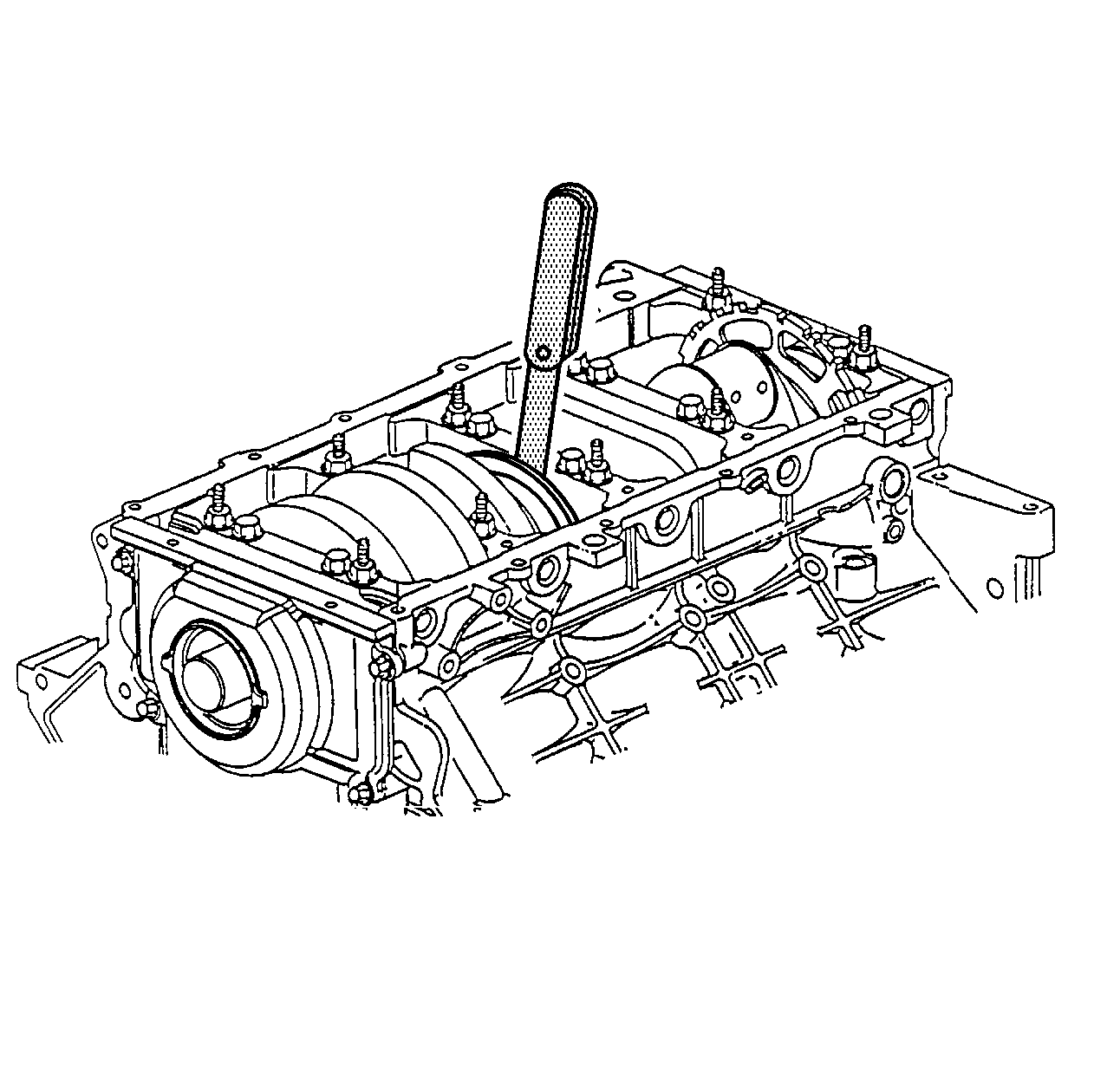
| 12.1. | Thrust the crankshaft forward or rearward. |
| 12.2. | Insert a feeler gage between the center crankshaft bearing and the bearing surface of the crankshaft and measure the bearing clearance. |
The proper crankshaft end play clearance is 0.04-0.2 mm (0.0015-0.0078 in).
| 12.3. | If the bearing clearance is not within specifications, inspect the thrust surfaces for nicks, gouges or raised metal. Minor imperfections may be removed with a fine stone. |
