Circuit Description
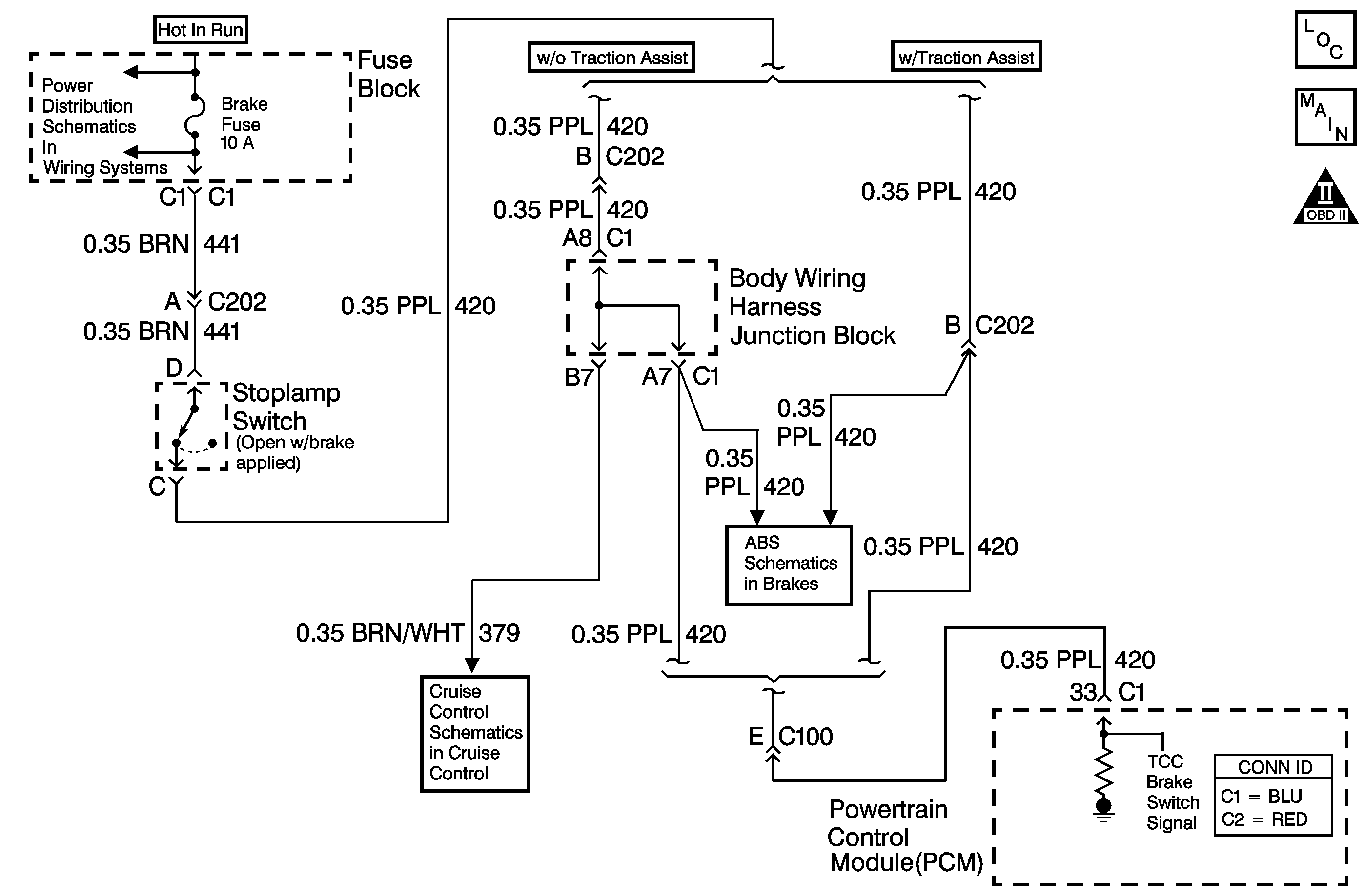
The TCC/Stop lamp switch indicates the brake pedal status. The normally closed brake switch supplies a B+ signal to the powertrain control module (PCM). The signal voltage circuit opens when the brake pedal is applied.
If the PCM detects a closed TCC/Stop lamp switch during decelerations, then DTC P0724 sets. DTC P0724 is a type C DTC.
Conditions for Running the DTC
| • | No AT VSS DTC P0502 or P0503. |
| • | The following sequence of events occurs 10 consecutive times: |
| 1. | The vehicle speed is greater than 40 km/h (25 mph) for 7 seconds. |
| 2. | Then the vehicle speed is 8-40 km/h (5-25 mph) for 2.5 seconds. |
| 3. | Then the vehicle speed is less than 8 km/h (5 mph). |
Conditions for Setting the DTC
| • | All conditions are met for 10 occurrences. |
| • | The PCM detects a closed TCC/Stop lamp switch circuit, 12 volts, during decelerations. |
Action Taken When the DTC Sets
| • | The PCM does not illuminate the malfunction indicator lamp (MIL). |
| • | The PCM records the operating conditions when the Conditions for Setting the DTC are met. The PCM stores this information as Failure Records. |
| • | The PCM stores DTC P0724 in PCM history. |
Conditions for Clearing the DTC
| • | A scan tool clears the DTC from PCM history. |
| • | The PCM clears the DTC from PCM history if the vehicle completes 40 warm-up cycles without a non-emission related diagnostic fault occurring. |
| • | The PCM cancels the DTC default actions when the fault no longer exists and the ignition switch is OFF long enough in order to power down the PCM. |
Diagnostic Aids
Inspect the brake switch for proper mounting and operation.
Test Description
The number below refers to the step number on the diagnostic table.
Step | Action | Value(s) | Yes | No |
|---|---|---|---|---|
1 | Did you perform the Powertrain Diagnostic System Check? | -- | Go to Step 2 | Go to Diagnostic System Check - Engine Controls in Engine Controls - 6.0L or Diagnostic System Check - Engine Controls in Engine Controls - 8.1L |
2 |
Important: Before clearing the DTCs, use the scan tool in order to record the Failure Records. Using the Clear Info function erases the Failure Records from the PCM. Caution: When you are performing service on or near the SIR components or the SIR wiring, you must disable the SIR system. Refer to Disabling the SIR System. Failure to follow the correct procedure could cause air bag deployment, personal injury, or unnecessary SIR system repairs. Did the TCC Brake Switch status change from CLOSED to OPEN? | -- | Go to Intermittent Conditions in Engine Controls - 6.0L or Intermittent Conditions in Engine Controls - 8.1L | Go to Step 3 |
Did the TCC Brake Switch status change from CLOSED to OPEN? | -- | Go to Step 4 | Go to Step 5 | |
4 | Replace the stop lamp switch. Refer to Stop Lamp Switch Replacement in Hydraulic Brakes. Did you complete the replacement? | -- | Go to Step 7 | -- |
5 |
Important: The condition that affects this circuit may exist in other connecting branches of the circuit. Refer to Power Distribution Schematics in Wiring Systems for complete circuit distribution. Test the TCC brake switch signal circuit (CKT 420) for a short to voltage. Did you find and correct the condition? | -- | Go to Step 7 | Go to Step 6 |
6 | Replace the PCM. Refer to Powertrain Control Module Replacement in Engine Controls - 6.0L or Powertrain Control Module Replacement in Engine Controls - 8.1L. Did you complete the replacement? | -- | Go to Step 7 | -- |
7 | Perform the following procedure in order to verify the repair:
Does the scan tool TCC Brake Switch status change from CLOSED to OPEN? | -- | System OK | Go to Step 1 |
