DTC P0503 Vehicle Speed Sensor (VSS) Circuit Intermittent 4.3L
Circuit Description
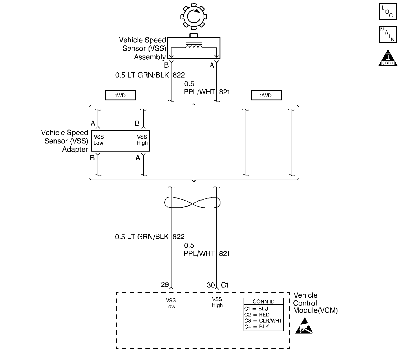
The vehicle speed sensor (VSS) assembly provides vehicle speed information to the vehicle control module (VCM). The VSS assembly is a permanent magnet (PM) generator. The PM generator produces a pulsing AC voltage as rotor teeth on the output shaft of the transmission (2WD) or transfer case (4WD) pass through the sensor's magnetic field. The AC voltage level and the number of pulses increase as the speed of the vehicle increases. The VCM converts the pulsing voltage to vehicle speed. The VCM uses the vehicle speed signal to determine shift timing and torque converter clutch (TCC) scheduling.
When the VCM detects an unrealistically large drop in vehicle speed, then DTC P0503 sets. DTC P0503 is a type B DTC.
Conditions for Running the DTC
| • | No TFP manual valve position switch DTC P1810. |
| • | The engine speed is greater than 450 RPM for 5 seconds. |
| • | The engine is not in fuel cutoff. |
| • | The time since the last gear range change is greater than 6 seconds. |
| • | The transmission output speed rise does not exceed 600 RPM within 6 seconds. |
Conditions for Setting the DTC
The transmission output speed drops by greater than 1300 RPM for 3 seconds when the transmission is not in PARK or NEUTRAL.
Action Taken When the DTC Sets
| • | The VCM illuminates the malfunction indicator lamp (MIL) during the second consecutive trip in which the conditions for setting the DTC are met. |
| • | The VCM commands second gear only. |
| • | The VCM commands maximum line pressure. |
| • | The VCM freezes shift adapts from being updated. |
| • | The VCM inhibits TCC engagement. |
| • | The VCM inhibits fourth gear if the transmission is in hot mode. |
| • | The VCM stores DTC P0503 in VCM history during the second consecutive trip in which the conditions for setting the DTC are met. |
Conditions for Clearing the MIL/DTC
| • | The VCM turns OFF the MIL during the third consecutive trip in which the diagnostic test runs and passes. |
| • | A scan tool clears the DTC from VCM history. |
| • | The VCM clears the DTC from VCM history if the vehicle completes 40 warm-up cycles without an emission-related diagnostic fault occurring. |
| • | The VCM cancels the DTC default actions when the fault no longer exists and the ignition switch is OFF long enough in order to power down the VCM. |
Diagnostic Aids
| • | Inspect the wiring at the VCM, the VSS connector and all other circuit connecting points for the following conditions: |
| - | A backed out terminal |
| - | A damaged terminal |
| - | Reduced terminal tension |
| - | A chafed wire |
| - | A broken wire inside the insulation |
| - | Moisture intrusion |
| - | Corrosion |
| • | When diagnosing for an intermittent short or open condition, massage the wiring harness while watching the test equipment for a change. |
Test Description
The numbers below refer to the step numbers on the diagnostic table.
-
This step tests the VSS assembly circuit.
-
This step tests the integrity of the VSS assembly.
-
This step tests the 5-volt and ground circuits of the VCM.
Step | Action | Value(s) | Yes | No |
|---|---|---|---|---|
1 | Was the Powertrain On-Board Diagnostic (OBD) System Check performed? | -- | Go to Powertrain On Board Diagnostic (OBD) System Check in Engine Controls | |
2 |
Important: Before clearing the DTC, use the scan tool in order to record the Freeze Frame and Failure Records. Using the Clear Info function erases the Freeze Frame and Failure Records from the VCM. Does the scan tool Transmission OSS drop or fluctuate more than the specified value? | 1300 RPM | Go to Diagnostic Aids | |
Is the resistance within the specified range? | 1377-3355 ohms (2WD) 976-2354 ohms (4WD) | |||
4 | Measure the resistance between terminal C1-30 and ground. Is the resistance greater than the specified value? | 50 K ohms | ||
Is the voltage greater than the specified value? | 0.5 volts | |||
6 |
Refer to General Electrical Diagnosis in Wiring Systems. Refer to Wiring Repairs in Wiring Systems. Did you find an open condition? | -- | ||
7 |
Refer to General Electrical Diagnosis in Wiring Systems. Refer to Wiring Repairs in Wiring Systems. Did you find a short to ground condition? | -- | Go to Diagnostic Aids | |
Is the voltage within the specified range? | 4.0-5.1 volts | |||
9 |
Did you find a damaged condition? | -- | ||
10 |
Important: For vehicles equipped with an active transfer case, identify the VSS assembly before replacing. There are two transfer case speed sensors located near the VSS assembly. Refer to the wire colors on the schematic to identify the VSS assembly. Replace the VSS assembly. Refer to Vehicle Speed Sensor Replacement . Is the replacement complete? | -- | -- | |
11 | Was the voltage measured in Step 8 less than the voltage in the value column? | 4.0 volts | ||
12 | Was the voltage measured in Step 8 greater than the voltage in the value column? | 5.1 volts | -- | |
13 | Repair the short to B+ in circuit 821 (PPL/WHT). Refer to Wiring Repairs in Wiring Systems. Is the repair complete? | -- | -- | |
14 | Replace the VCM. Refer to VCM Replacement/Programming in Engine Controls. Is the replacement complete? | -- | -- | |
15 | Perform the following procedure in order to verify the repair:
Has the test run and passed? | -- | System OK |
DTC P0503 Vehicle Speed Sensor (VSS) Circuit Intermittent 4.8L and 5.3L
Circuit Description
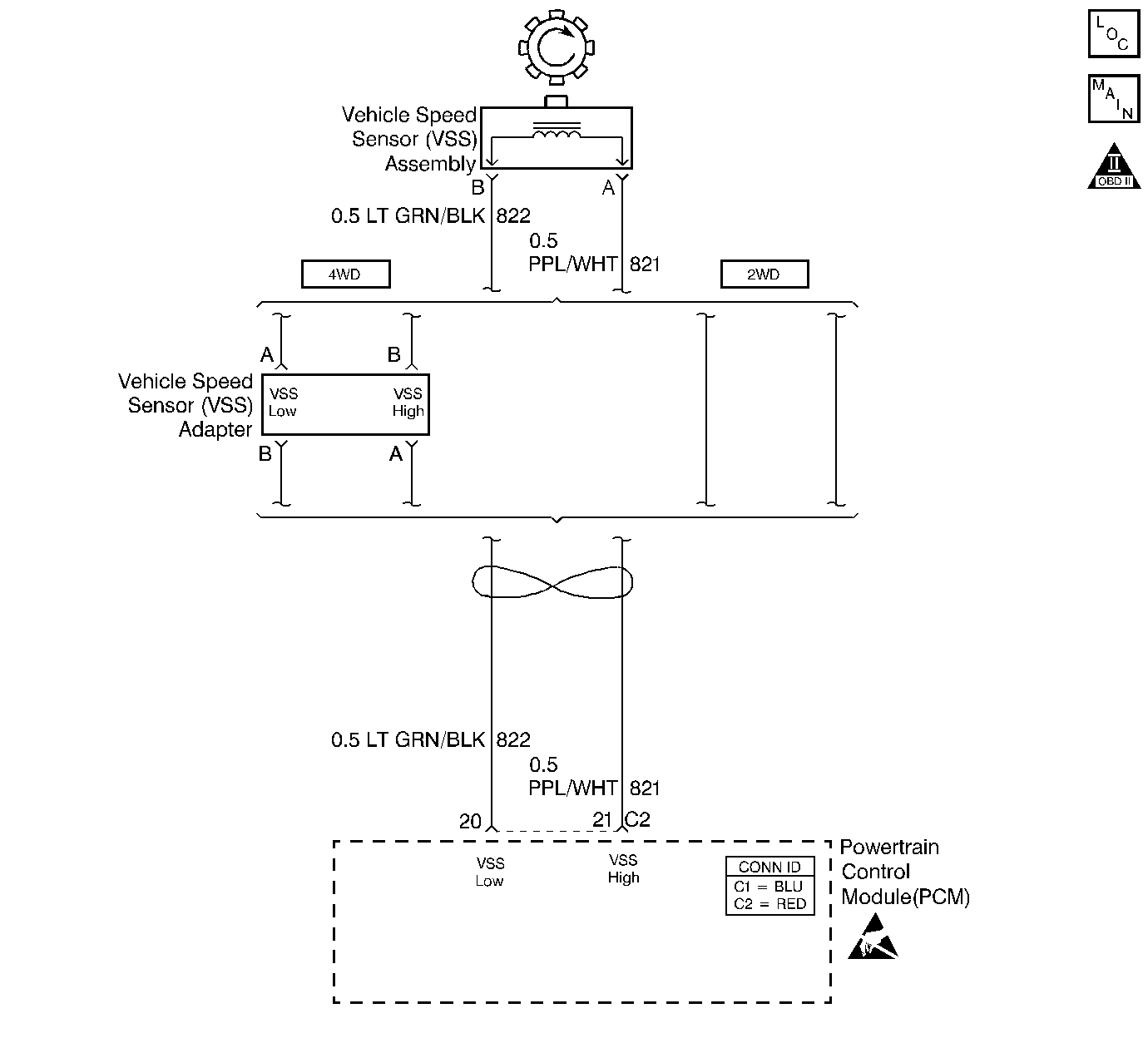
The vehicle speed sensor (VSS) assembly provides vehicle speed information to the powertrain control module (PCM). The VSS assembly is a permanent magnet (PM) generator. The PM generator produces a pulsing AC voltage as rotor teeth on the output shaft of the transmission (2WD) or transfer case (4WD) pass through the sensor's magnetic field. The AC voltage level and the number of pulses increase as the speed of the vehicle increases. The PCM converts the pulsing voltage to vehicle speed. The PCM uses the vehicle speed signal to determine shift timing and torque converter clutch (TCC) scheduling.
When the PCM detects an unrealistically large drop in vehicle speed, then DTC P0503 sets. DTC P0503 is a type B DTC.
Conditions for Running the DTC
| • | No TFP manual valve position switch DTC P1810. |
| • | The engine speed is greater than 300 RPM for 5 seconds. |
| • | The engine is not in fuel cutoff. |
| • | The time since the last gear range change is greater than 6 seconds. |
| • | The time since the last 4WD low state change is greater than 6 seconds. |
| • | The transmission output speed rise does not exceed 600 RPM within 6 seconds. |
Conditions for Setting the DTC
The transmission output speed drops by greater than 1300 RPM for 3 seconds when the transmission is not in PARK or NEUTRAL.
Action Taken When the DTC Sets
| • | The PCM illuminates the malfunction indicator lamp (MIL) during the second consecutive trip in which the conditions for setting the DTC are met. |
| • | The PCM commands second gear only. |
| • | The PCM commands maximum line pressure. |
| • | The PCM freezes shift adapts from being updated. |
| • | The PCM inhibits TCC engagement. |
| • | The PCM inhibits fourth gear if the transmission is in hot mode. |
| • | The PCM stores DTC P0503 in PCM history during the second consecutive trip in which the conditions for setting the DTC are met. |
Conditions for Clearing the MIL/DTC
| • | The PCM turns OFF the MIL during the third consecutive trip in which the diagnostic test runs and passes. |
| • | A scan tool clears the DTC from PCM history. |
| • | The PCM clears the DTC from PCM history if the vehicle completes 40 warm-up cycles without an emission-related diagnostic fault occurring. |
| • | The PCM cancels the DTC default actions when the fault no longer exists and the ignition switch is OFF long enough in order to power down the PCM. |
Diagnostic Aids
| • | Inspect the wiring at the PCM, the VSS connector and all other circuit connecting points for the following conditions: |
| - | A backed out terminal |
| - | A damaged terminal |
| - | Reduced terminal tension |
| - | A chafed wire |
| - | A broken wire inside the insulation |
| - | Moisture intrusion |
| - | Corrosion |
| • | When diagnosing for an intermittent short or open condition, massage the wiring harness while watching the test equipment for a change. |
Test Description
The numbers below refer to the step numbers on the diagnostic table.
Step | Action | Value(s) | Yes | No |
|---|---|---|---|---|
1 | Was the Powertrain On-Board Diagnostic (OBD) System Check performed? | -- | Go to Powertrain On Board Diagnostic (OBD) System Check in Engine Controls | |
2 |
Important: Before clearing the DTC, use the scan tool in order to record the Freeze Frame and Failure Records. Using the Clear Info function erases the Freeze Frame and Failure Records from the PCM. Does the scan tool Transmission OSS drop or fluctuate more than the specified value? | 1300 RPM | Go to Diagnostic Aids | |
Is the resistance within the specified range? | 1377-3355 ohms (2WD) 976-2354 ohms (4WD) | |||
4 | Measure the resistance from terminal C2-21 to ground. Is the resistance greater than the specified value? | 50 K ohms | ||
Is the voltage greater than the specified value? | 0.5 volts | |||
6 |
Is the resistance within the specified range? | 1377-3355 ohms (2WD) 976-2354 ohms (4WD) | ||
7 |
Refer to General Electrical Diagnosis in Wiring Systems. Refer to Wiring Repairs in Wiring Systems. Did you find a short to ground condition? | -- | Go to Diagnostic Aids | |
8 |
Refer to General Electrical Diagnosis in Wiring Systems. Refer to Wiring Repairs in Wiring Systems. Did you find an open condition? | -- | Go to Diagnostic Aids | |
9 |
Did you find a damaged condition? | -- | ||
10 |
Important: For vehicles equipped with an active transfer case, identify the VSS assembly before replacing. There are two transfer case speed sensors located near the VSS assembly. Refer to the wire colors on the schematic to identify the VSS assembly. Replace the VSS assembly. Refer to Vehicle Speed Sensor Replacement . Is the replacement complete? | -- | -- | |
11 | Replace the PCM. Refer to Powertrain Control Module Replacement/Programming in Engine Controls. Is the replacement complete? | -- | -- | |
12 | Perform the following procedure in order to verify the repair:
Has the test run and passed? | -- | System OK |
