RADIO SYSTEM DIAGNOSIS INFO USE TECH-1 OR T-100 FOR DIAG.

SUBJECT: RADIO DIAGNOSIS (INSTALLATION OF JUMPER WIRE FOR CAMS AND TECH 1 DIAGNOSIS)
MODELS: 1988-1992 C/K AND TOPKICK/KODIAK
Radio conditions may be more accurately diagnosed on C/K and TopKick/ Kodiak vehicles by using a Tech 1 or CAMS T-100. Radio system diagnosis with the Tech 1 requires body cartridge TKO3040B and the T-100 requires the use of ALDL E&C (Entertainment and Comfort) adapter, part number 56746.
On the aforementioned vehicles, the radio system consists of a radio control head, radio receiver, cassette deck, and graphic equalizer. The Tech 1 or T-100 when used can override and simulate the radio control head.
The Tech 1 or T-100 allows you to monitor or transmit messages to and from any radio system component.
This makes testing of the receiver, balance controls, volume, fader, individual speakers, clock, station select, and other features possible. The technician can then accurately attribute a given condition to a specific component rather than remove each of the separate units for diagnosis and repair.
Cassette tape player functions cannot be tested with this system; however, a more accurate diagnosis can still be made by verifying correct operation of the other system components. Please refer to the Tech 1 or T-100 handbook for more detailed entertainment system diagnosis information.
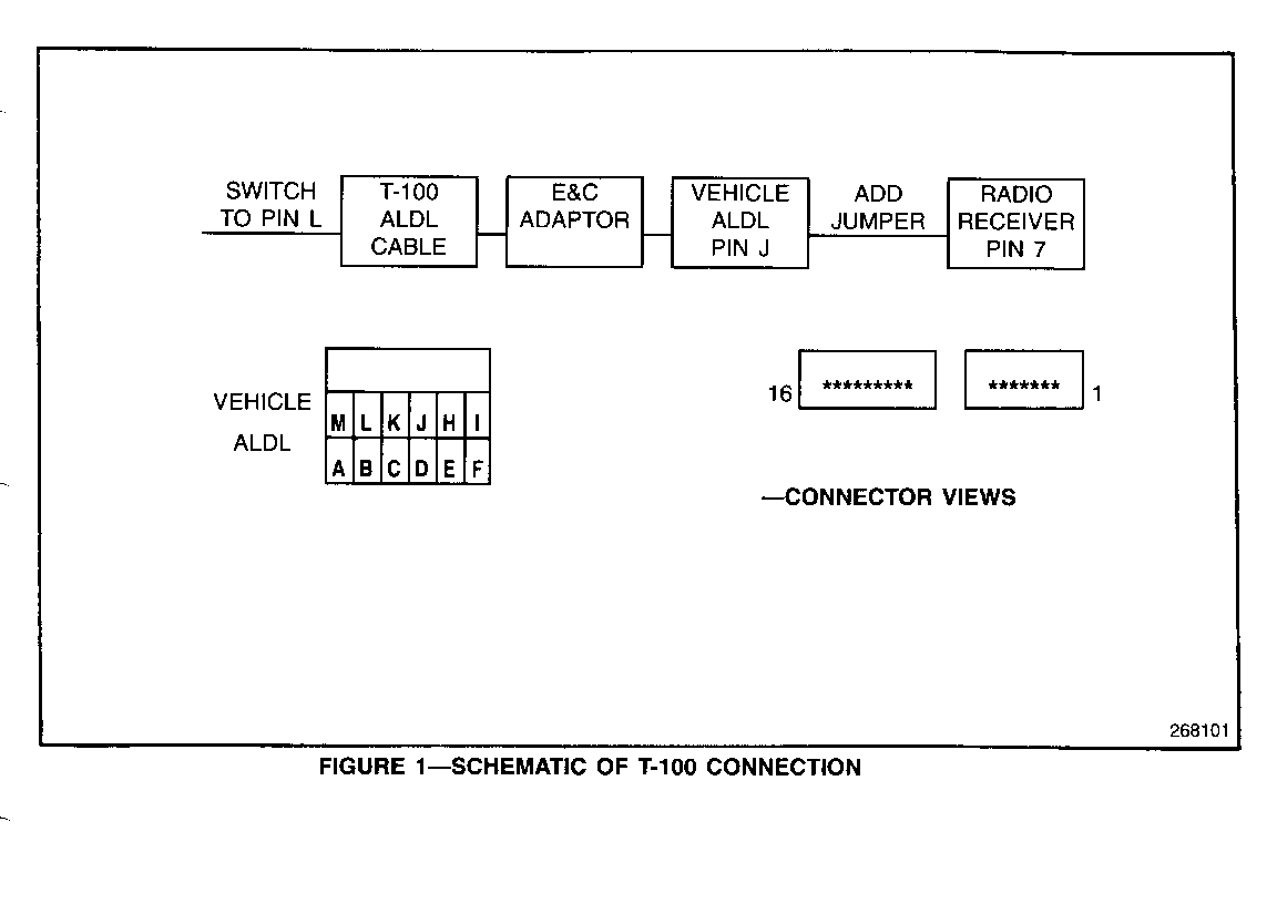
To apply Tech 1 or CAMS T-100 diagnostics to C/K or TopKick/Kodiak vehicles, a jumper wire between ALDL connector terminal "J" and the radio receiver must first be installed (Figure 1).
SERVICE PROCEDURE:
1. Remove lower steering trim panel.
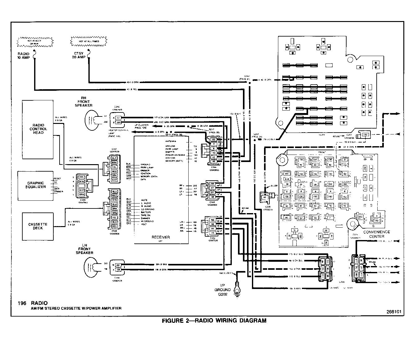
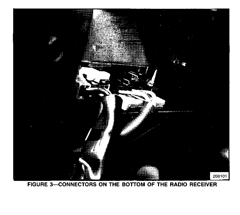
2. Locate the six wire connector going into the bottom of the radio receiver at location C247. Please refer to the appropriate 1992 ELECTRI- CAL DIAGRAM AND DIAGNOSIS MANUAL (Figures 2 and 3).
3. Locate the white wire (pin 6) in this six wire connector. Also locate the unused pin in the seventh position on the radio receiver. Both the white wire in the sixth position and the open unused seventh pin are serial data terminals. The open pin on the radio receiver in position seven is not shown on the electrical wiring diagram. The six wire connector is visible from under the dash and is quite accessible (Figure 3).
4. Using a 16-inch piece of 0.8 GA wire, make a jumper wire to install between ALDL terminal J and the open seventh position pin of the radio receiver. Use a wire with white insulation to indicate a serial data line.
The connection at the ALDL location can be made with terminal part number 12077411. The connection at the radio receiver can be made with terminal part number 12047767. These terminals are included in Packard Electric terminal repair kit J38125.
5. After the jumper wire is made, remove the six wire connector from the radio receiver. Plug in the jumper wire on pin seven. Reinstall the six wire connector.
Note that the terminal connection to pin seven is a friction fit to the pin. The terminal does not clip into place.
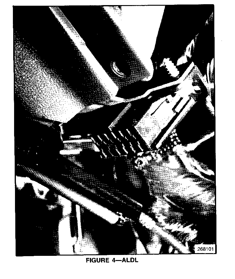
6. Connect the opposite end of the jumper wire to ALDL terminal J (Figure 4).
7. Using wire ties, secure the jumper wire to the existing instrument panel harness (leave the wire in place after diagnosis).
8. Proceed with normal diagnosis using either the Tech 1 or CAMS T-100
SERVICE PARTS INFORMATION:
Part Number Description Quantity ----------- ----------- -------- 12077411 Terminal 1 12047767 Terminal 1 Procure Locally 0.8 Gage White Wire 18"
WARRANTY INFORMATION:
If the vehicle is repaired under warranty use:
Labor Operation: T7446 Labor Time: 0.4 hrs.
Note: Labor Operation is coded to base vehicle warranty coverage in the Warranty System.
General Motors bulletins are intended for use by professional technicians, not a "do-it-yourselfer". They are written to inform those technicians of conditions that may occur on some vehicles, or to provide information that could assist in the proper service of a vehicle. Properly trained technicians have the equipment, tools, safety instructions and know-how to do a job properly and safely. If a condition is described, do not assume that the bulletin applies to your vehicle, or that your vehicle will have that condition. See a General Motors dealer servicing your brand of General Motors vehicle for information on whether your vehicle may benefit from the information.
