Removal Procedure
Important:
| • | The brake pedal drive motor, drive cable, and transmission for the electronic adjustable pedal (EAP) are not serviced separately, but as a unit. The new drive motor assembly will be preset in full forward position. |
| • | The EAP must be set to the full forward position whenever work is done on or around the pedal assembly. |
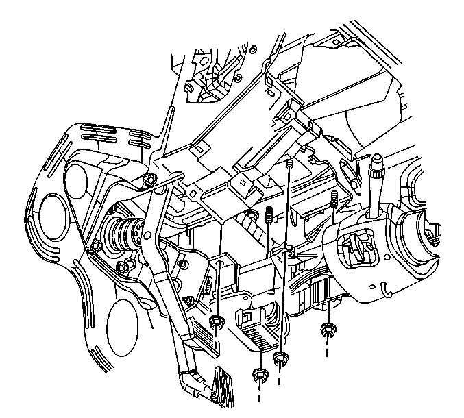
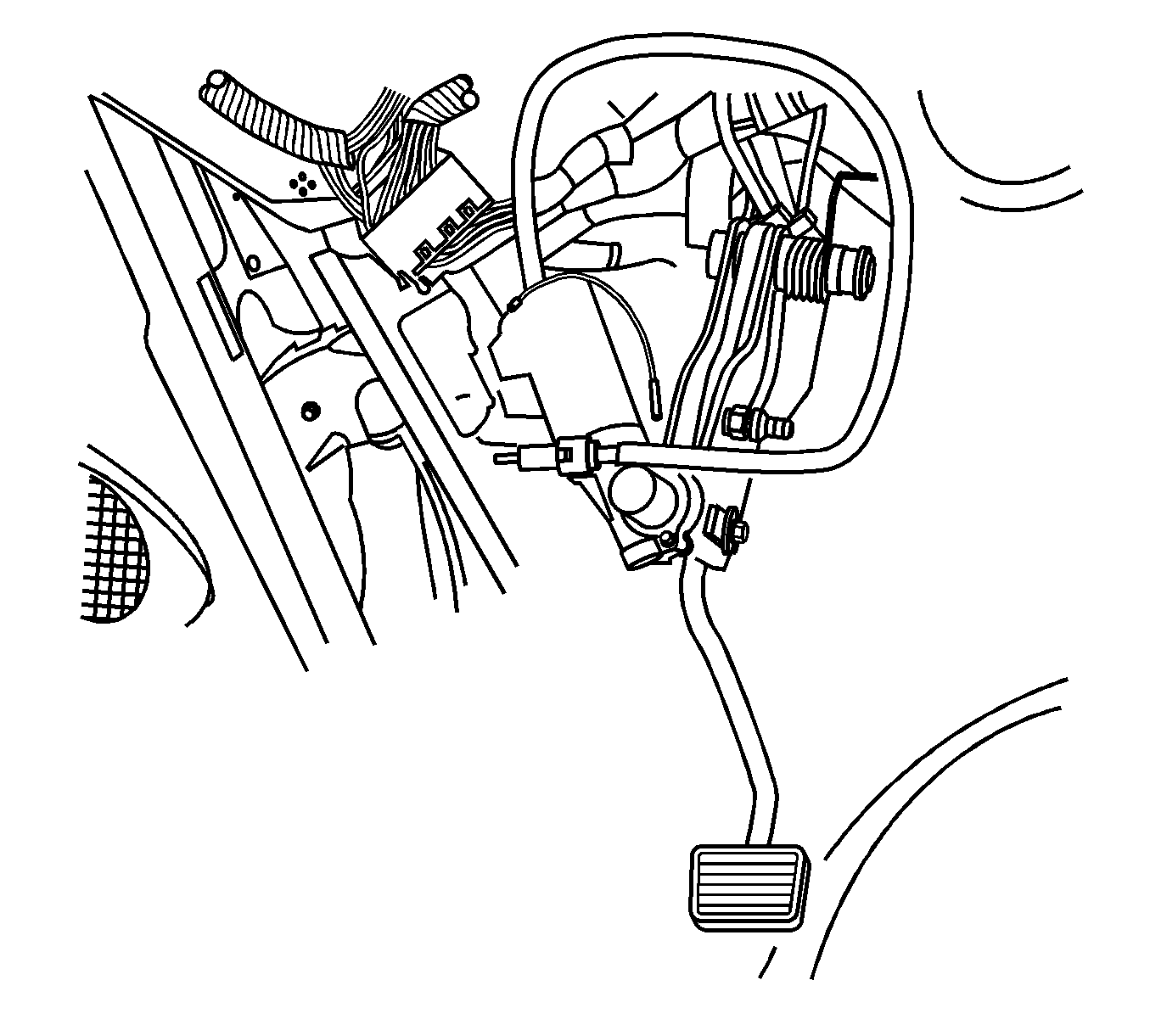
- Remove the steering column. Refer to
Steering Column Replacement
.
Important: The accelerator pedal must be set in the full forward position before the brake pedal assembly can be replaced. If the accelerator pedal cannot be adjusted to the full forward position, because of a faulty drive cable
or drive motor, perform the following service procedure:
- Adjust the accelerator pedal in the following manner:
| 2.2. | Install the drive cable to the accelerator pedal. |
| 2.3. | Attach a variable speed electric hand drill to the drive cable. |
| 2.4. | Set the drill motor on the slowest speed. If the drill motor has a clutch setting, set it on the weakest or lowest setting allowing the drive cable to rotate. |
| 2.5. | Rotating the drive cable in a clockwise rotation, move the accelerator pedal to the full forward position. |
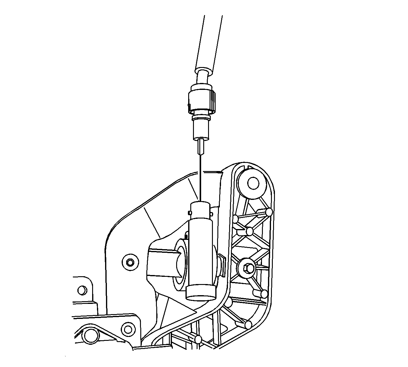
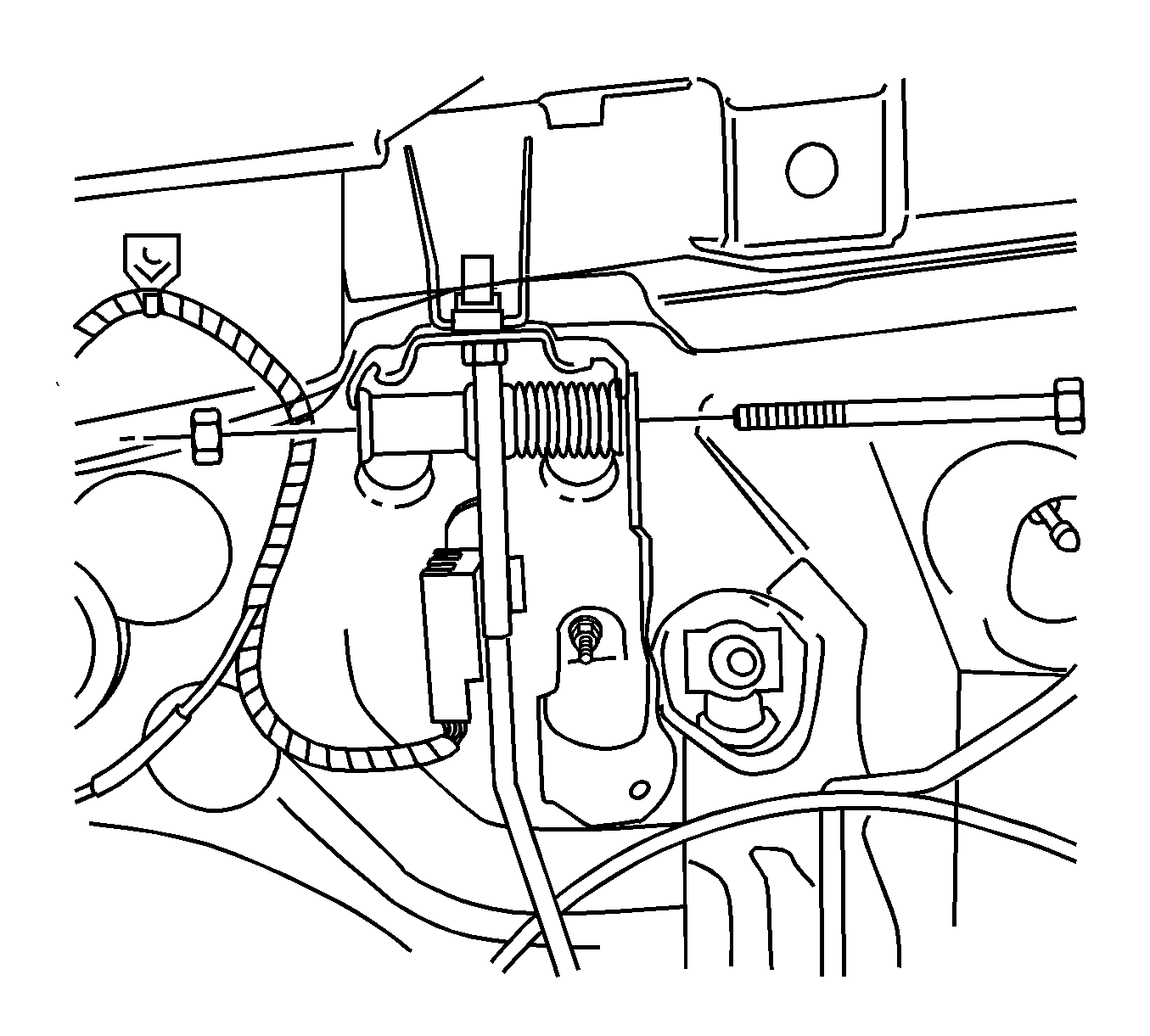
- Remove the electrical connector from the drive motor.
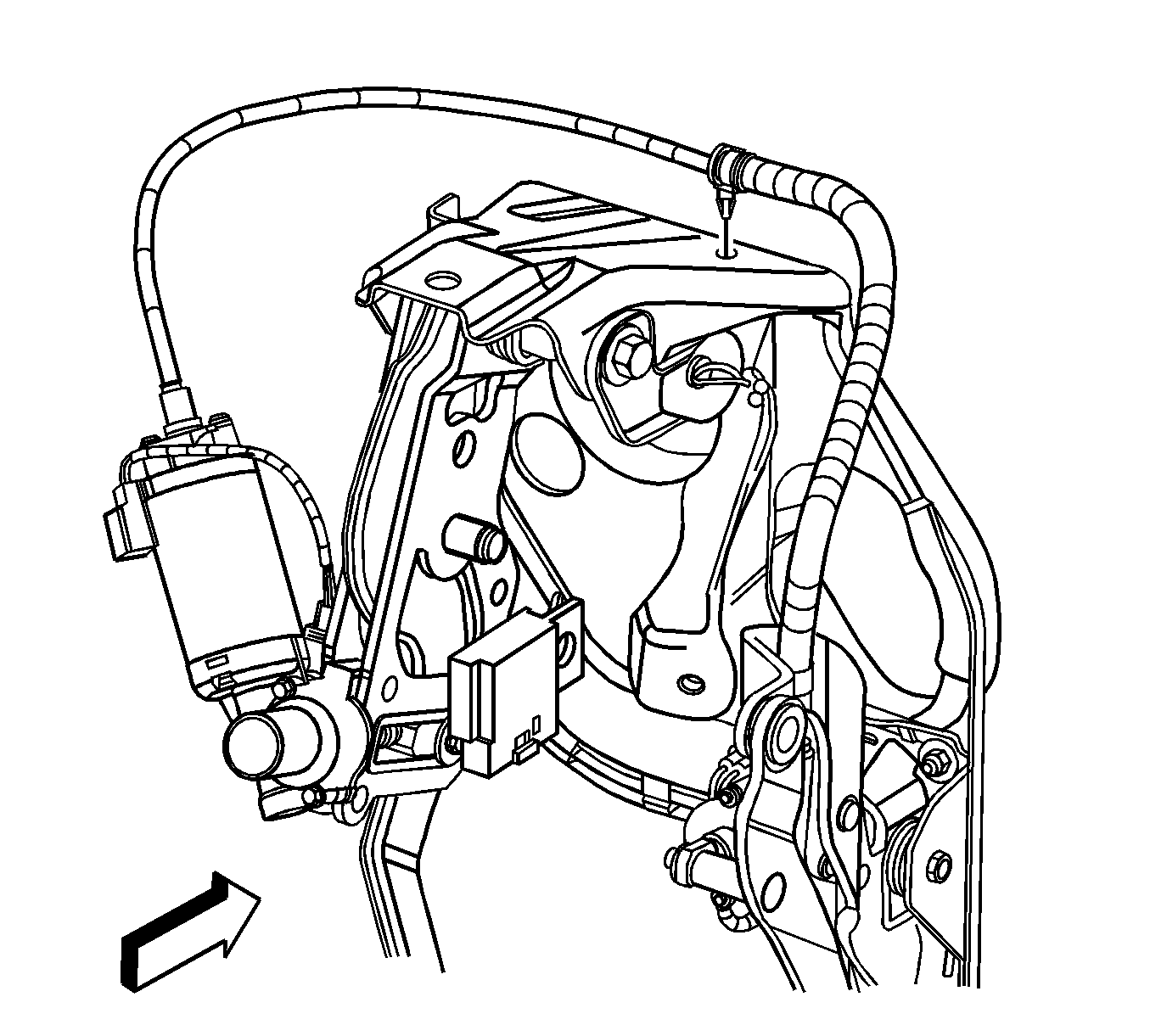
- Remove the drive cable retainer bracket at the right upper corner of the steering
column support bracket.
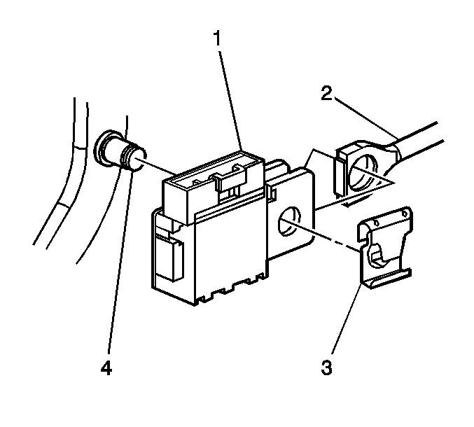
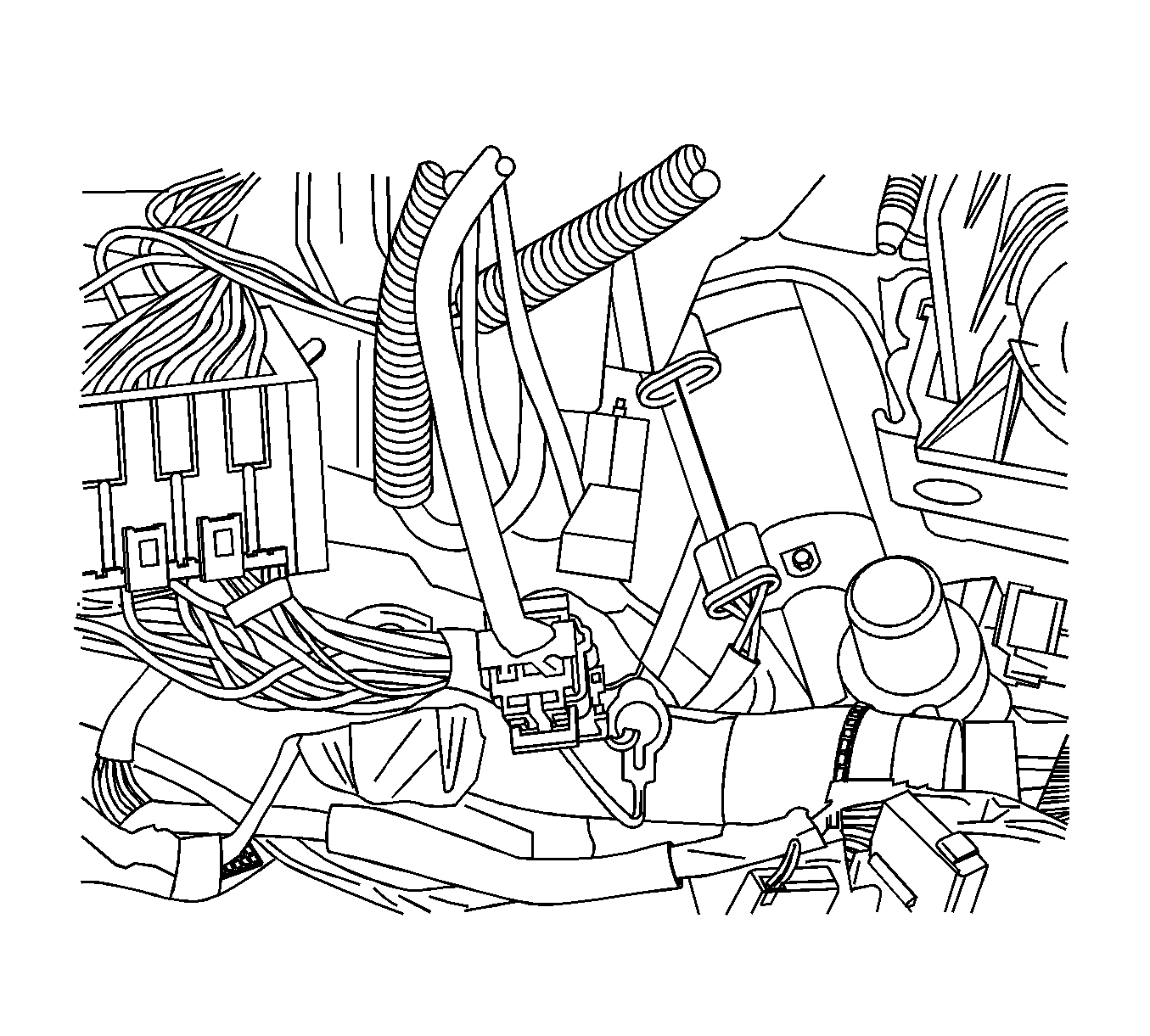
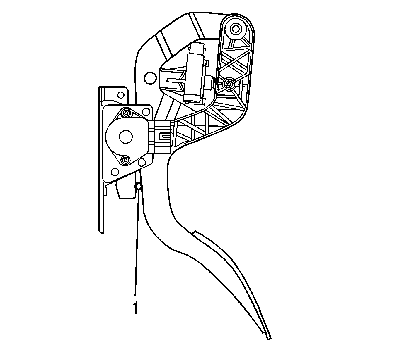
- Remove the electrical connector for the brake light switch (1).
- Remove the retaining clip (3) from the brake pedal (4).
- Remove the brake light switch (1) from the brake pedal (4).
- Remove the brake light switch (1) from the pushrod (2).
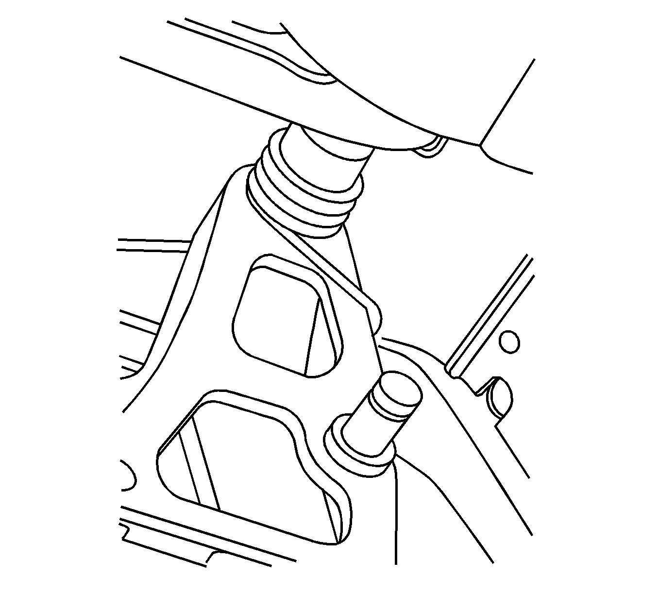
- Remove the brake pedal pivot bolt and nut.
- Remove the brake pedal assembly from the steering column support bracket.
Installation Procedure
Important: When installing the brake pedal assembly, ensure that the bushing is in the proper position and the return spring is properly seated against the brake pedal.
- Install the brake pedal return spring.
- Install the brake pedal assembly to the steering column support bracket.
Notice: Refer to Fastener Notice in the Preface section.
- Install the pivot bolt and nut.
Tighten
Tighten the pivot bolt and nut to 25 N·m (18 lb ft).
- Install the brake light switch (1) on the pushrod (2).
- Install the pushrod (2) on the brake pedal (4).
- Install the retaining clip (3) on the brake pedal (4).
- Install the electrical connector to the brake switch (1).
- Install the electrical connector to the brake pedal drive motor.
- Install the drive cable retainer to the upper right corner of the steering column
support.
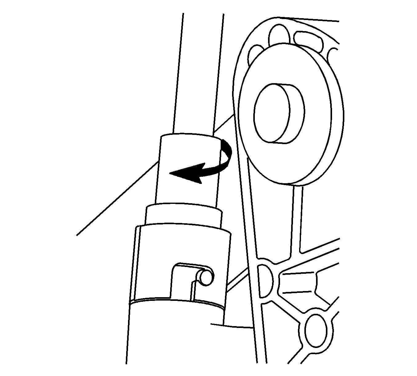
Important: The following procedure must be performed before the installation of the drive motor and cable assembly. Failure to do so could cause an IMPROPER STEP OVER HEIGHT.
- Adjust the accelerator pedal in the following manner:
| 10.1. | Turning the motor transmission clockwise reduces the gap, and counterclockwise increases the gap. |
| 10.2. | Position the drill bit 4.5 mm (0.187 in, 3/16 or the equivalent in number and or letter drill bits) a 1/4 of an inch from the bottom of the metal accelerator pivot arm. |
| 10.3. | Rotating the drive cable by hand, adjust the accelerator motor transmission until the drill 4.5 mm (0.187 in, 3/16 or the equivalent in number and or letter drill) bit fits snugly between the plastic accelerator arm and the metal pivot
arm. |
- Install the drive cable in the accelerator pedal.
- Rotate and lock the driver cable collar.
- Install the steering column assembly. Refer to
Steering Column Replacement
.
- Verify the operation of the adjustable pedals.
