Tools Required
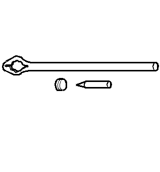
| • | J 8614-01 Flange and Pulley Holding Tool |
| • | J 33782 Pinion Oil Seal Installer |
Removal Procedure
- Raise the vehicle. Refer to Lifting and Jacking the Vehicle .
- Remove the engine protection shield. Refer to Engine Protection Shield Replacement .
- Drain the drive axle. Refer to Front Axle Lubricant Replacement .
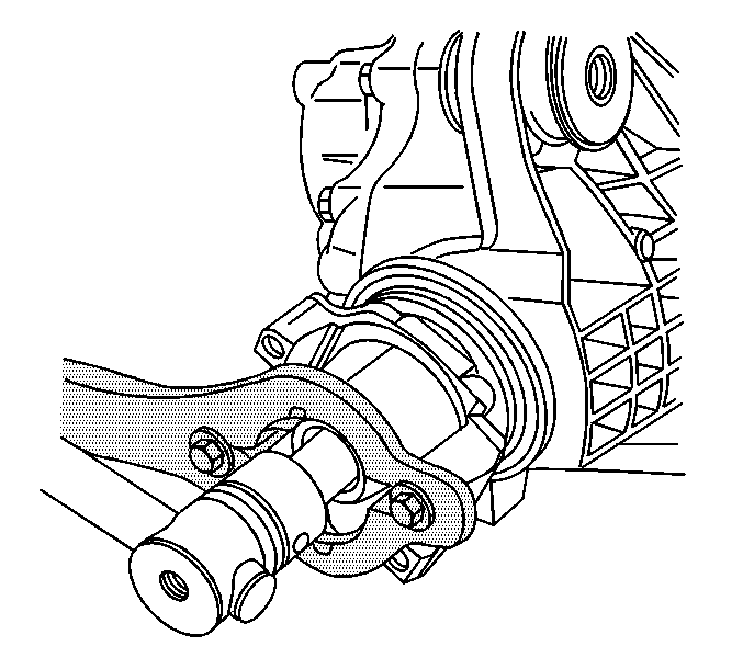
- Remove the front propeller shaft. Refer to Front Propeller Shaft Replacement .
- Remove the rear steering gear crossmember. Refer to Rear Steering Gear Crossmember Replacement .
- Measure the torque required in order to rotate the pinion. Use an inch-pound torque wrench. Record the torque value for reassembly. This will give the combined preload for the following components:
- Scribe an alignment line between the pinion shaft and the pinion yoke.
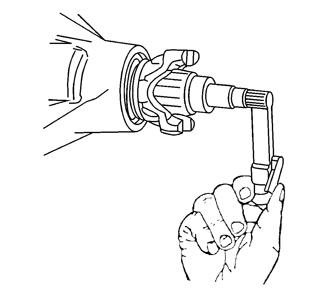
- Install the J 8614-01 onto the pinion as shown.
- Remove the pinion nut while holding the J 8614-01 .
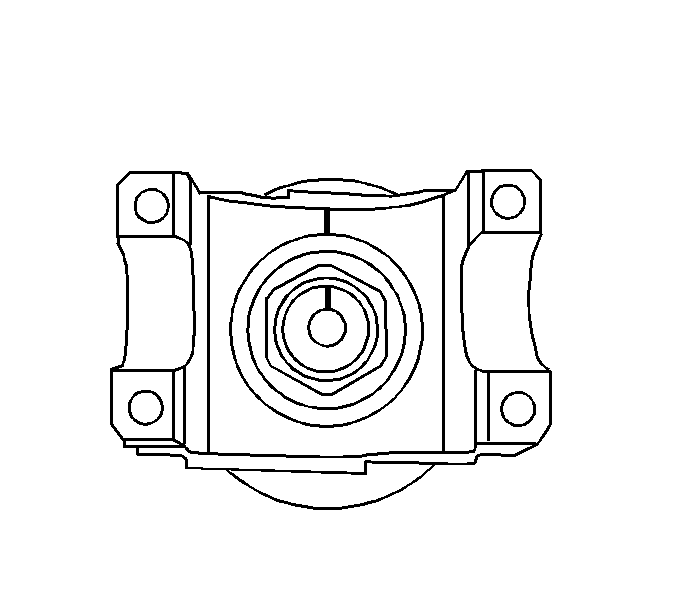
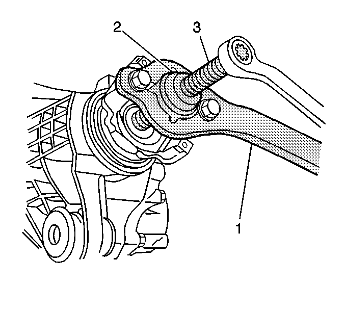
- Install the J 8614-2 (2) and the J 8614-3 (3) into the J 8614-01 (1) as shown.
- Remove the pinon yoke by turning the J 8614-3 (3) clockwise while holding the J 8614-01 (1).
- Remove the oil seal using a suitable seal removal tool.
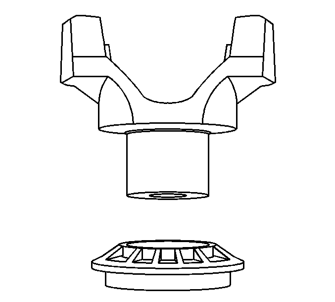
- Remove the dust deflector from the pinion yoke using a soft-faced hammer.
| • | The pinion bearings |
| • | The pinion seal |
| • | The carrier bearings |
| • | The axle bearings |
| • | The axle seals |
Important: Carefully remove the seal from the bore. Do not distort or scratch the aluminum case.
Installation Procedure
- Install the new deflector onto the pinion yoke using a soft-faced hammer.
- Install the new oil seal by doing the following:
- Apply sealant GM P/N 12346004 (Canadian P/N 10953480) or equivalent to the splines of the drive pinion yoke.
- Install the pinion yoke.
- Seat the pinion yoke onto the pinion shaft by tapping it with a soft-faced hammer until a few pinion shaft threads show through the yoke.
- Install the washer and a new pinion nut.
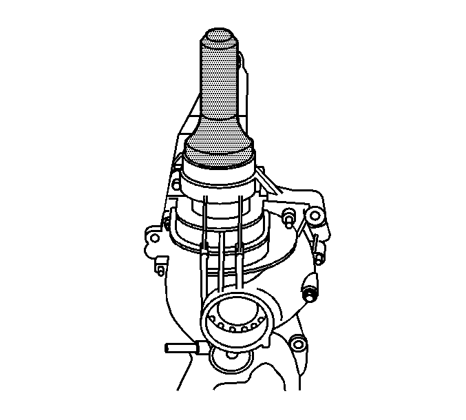
- Install the J 8614-01 onto the pinion yoke as shown.
- Tighten the pinion nut while holding the J 8614-01 .
- Measure the rotating torque of the pinion using an inch-pound torque wrench.
- If the rotating torque is not within specifications, continue to tighten the pinion nut.
- Once the specified torque is obtained, rotate the pinion several times to ensure the bearings have seated. Recheck the rotating torque and adjust if necessary.
- Install the rear steering gear crossmember. Refer to Rear Steering Gear Crossmember Replacement .
- Install the front propeller shaft. Refer to Front Propeller Shaft Replacement .
- Install the engine protection shield. Refer to Engine Protection Shield Replacement .
- Fill the drive axle. Refer to Front Axle Lubricant Replacement .
- Lower the vehicle.
Important: Drive the seal in straight, not at an angle, as this will damage the aluminum housing.
| 2.1. | Position the oil seal in the bore. |
| 2.2. | Install the J 33782 over the oil seal. |
| 2.3. | Strike the J 33782 with a hammer until the seal flange seats on the axle housing surface. |
Align the reference marks made during removal.
Notice: Do not hammer the pinion flange/yoke onto the pinion shaft. Pinion components may be damaged if the pinion flange/yoke is hammered onto the pinion shaft.
Notice: Use the correct fastener in the correct location. Replacement fasteners must be the correct part number for that application. Fasteners requiring replacement or fasteners requiring the use of thread locking compound or sealant are identified in the service procedure. Do not use paints, lubricants, or corrosion inhibitors on fasteners or fastener joint surfaces unless specified. These coatings affect fastener torque and joint clamping force and may damage the fastener. Use the correct tightening sequence and specifications when installing fasteners in order to avoid damage to parts and systems.
Important: If the rotating torque is exceeded, the pinion will have to be removed and a new collapsible spacer installed.
Tighten
Tighten the pinion nut until the pinion end play is just taken up. Rotate the pinion while tightening the nut to seat the bearings.
Compare the measurement of the rotating torque to the measurement recorded earlier.
Specification
The rotating torque of the pinion nut should be 0.40-0.57 N·m (3-5 lb in) greater than the torque recorded during removal.
Tighten
Tighten the pinion nut, in small increments, as needed, until the torque required in order to rotate the pinion is 0.40-0.57 N·m (3-5 lb in) greater than the torque recorded during removal.
