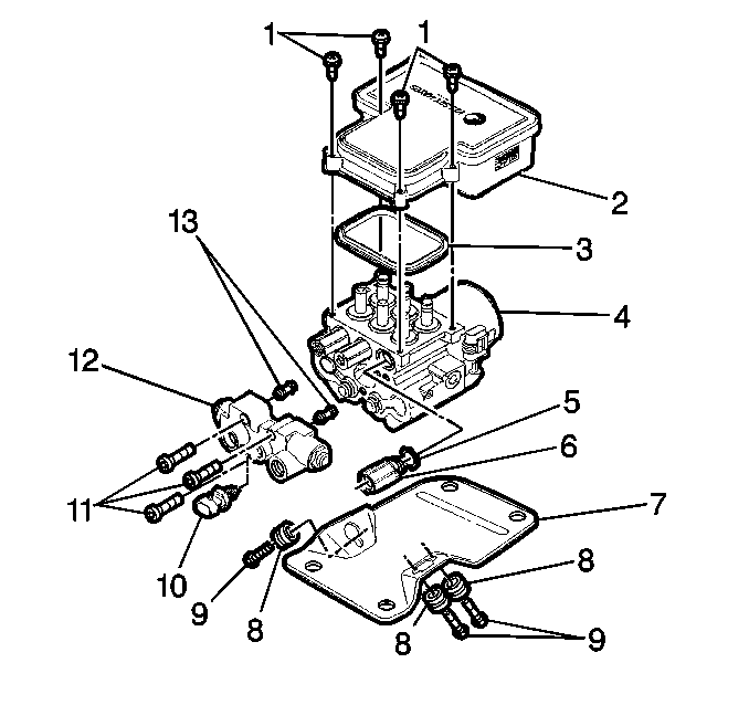
Removal Procedure
- Disconnect the negative battery cable.
- Remove the two fuse block mounting bolts from the EBCM bracket.
- Disconnect the electrical connector from the combination valve (12).
- Remove the front and rear brake pipes (from master cylinder) from the combination valve.
- Remove the right front, left front and rear brake pipes from the tube adapters (6).
- Remove the four 10 mm bolts (9) that fasten the EHCU bracket (7) to the vehicle mounting bracket.
- Lift the EHCU partially out or the engine compartment.
- Disconnect the four electrical connectors from EBCM (2).
- Fully remove the EHCU from the vehicle.
- Remove the three Allen bolts (11) from the combination valve (12).
- Remove the combination valve (12).
- Remove the two transfer tubes (13).
- Remove the three 13 mm bolts (9) that fasten the bracket to the BPMV.
- Remove the four T-25 Torx® bolts (1) from the EBCM.
- Remove the EBCM (2) from the BPMV (4). Removal may require a light amount of force.
Caution: Refer to Battery Disconnect Caution in the Preface section.

Important: Do not reuse the transfer tubes. Always install new transfer tubes.
Important: Do not use a tool to pry the EBCM or the BPMV. Excessive force will damage the EBCM.
Installation Procedure
- Install the new transfer tubes (13) into the combination valve into the combination valve (9).
- Install the combination valve onto the BPMV (4).
- Install the three Allen bolts (11) that fasten the combination valve (12) to the BPMV (4).
- Install the EBCM gasket (3) onto the BPMV (4).
- Ensure gasket alignment is correct.
- Install EBCM (2) onto BPMV (4).
- Install the four new EBCM bolts (1).
- Install EHCU (4) to bracket.
- Install the three BPMV (4) to bracket retaining bolts.
- Connect the four electrical connectors to the EBCM.
- Install the EHCU to the vehicle frame.
- Install the right front, left front and rear brake pipes to the tube adapters.
- Install the front and rear brake pipes (from master cylinder) to the combination valve.
- Connect the electrical connector to the combination valve.
- Install the two fuse block mounting bolts from the EBCM bracket.
- Connect the negative battery cable.
- Bleed the brake system. Refer to Antilock Brake System Automated Bleed Procedure .
- Return to Diagnostic System Check.

Tighten
Tighten the three Allen bolts to 8 N·m (6 lb ft),
then to 16 N·m (12 lb ft).
Important: Do not reuse the old EBCM mounting bolts. Always install new mounting bolts with the new EBCM.
Important: Do not use RTV or any other type of sealant on the EBCM gasket or mating surfaces.
Tighten
Tighten the four bolts to 5 N·m (39 lb. in.)
in an X-pattern.
Tighten
Tighten the three bolts to 9 N·m (7 lb ft).
Tighten
Tighten the three bolts to 25 N·m (20 lb ft).
Tighten
Tighten the three brake pipe fittings to 29 N·m (22 lb ft).
Tighten
Tighten the three brake pipe fittings to 29 N·m (22 lb ft).
Important: Verify that the combination valve metering rod is depressed during bleeding.
