Removal Procedure
- Disconnect the negative battery cable.
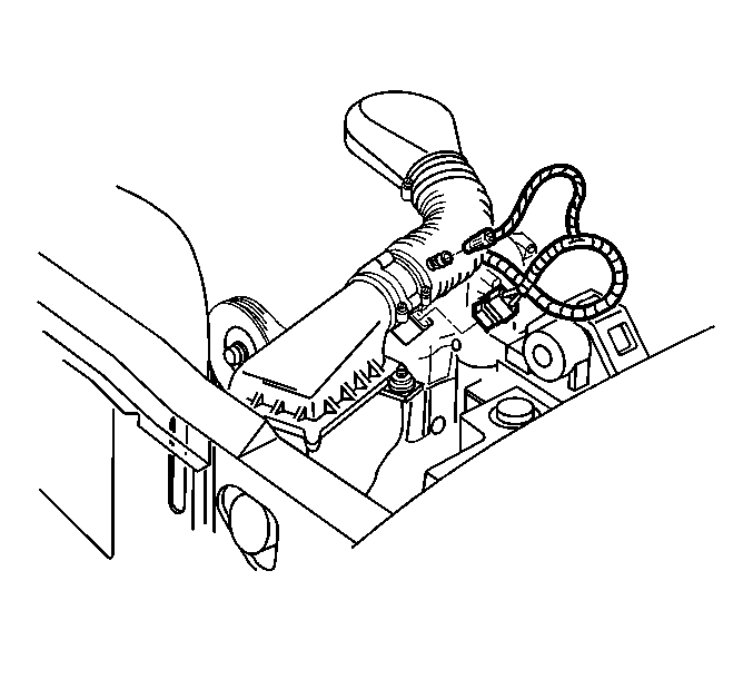
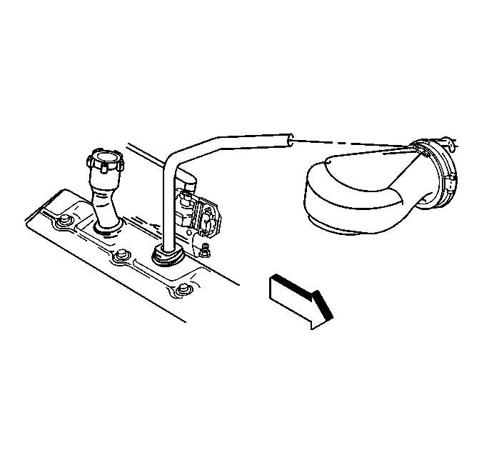
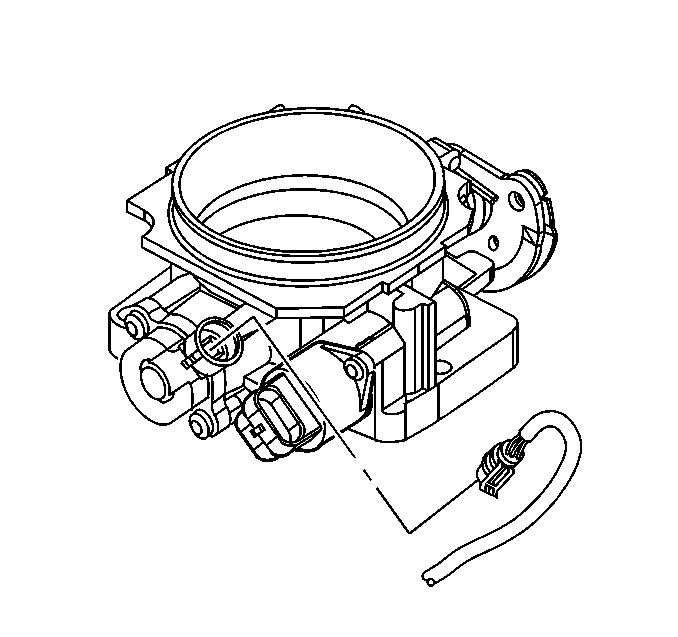
- Disconnect the IAT sensor harness connector.
- Disconnect the breather tube from the air cleaner outlet duct.
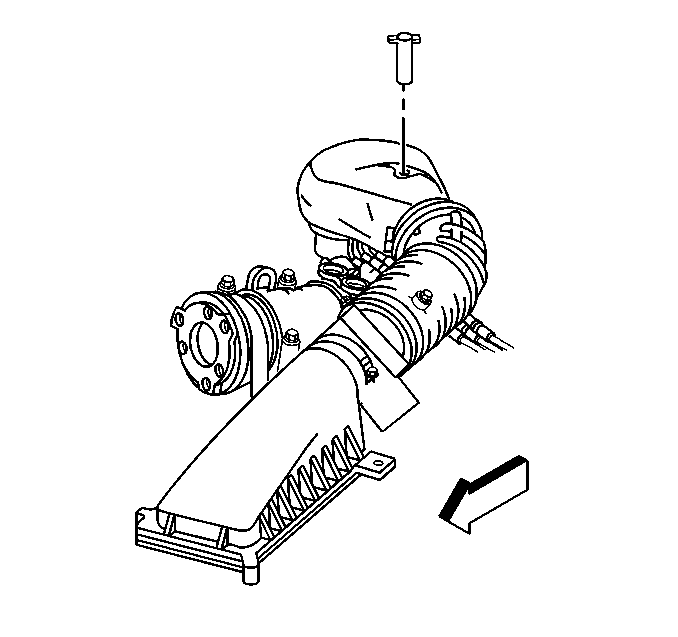
- Remove the wing nut retaining the air outlet duct.
- Loosen the clamp on the outlet of the MAF sensor.
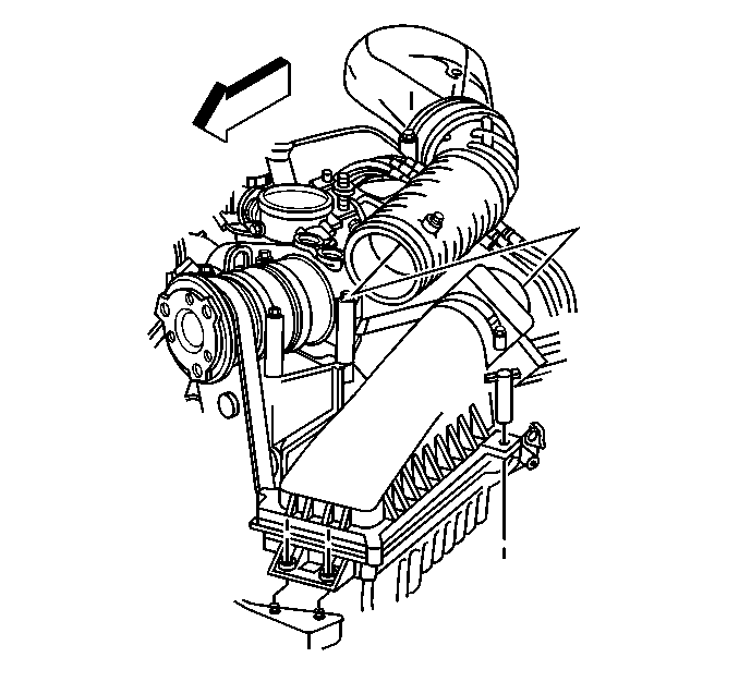
- Lift the air cleaner outlet duct from the throttle body and remove the assembly from the MAF sensor.
- Disconnect the TP sensor harness connector.
- Remove the throttle body. Refer to Throttle Body Assembly Replacement .
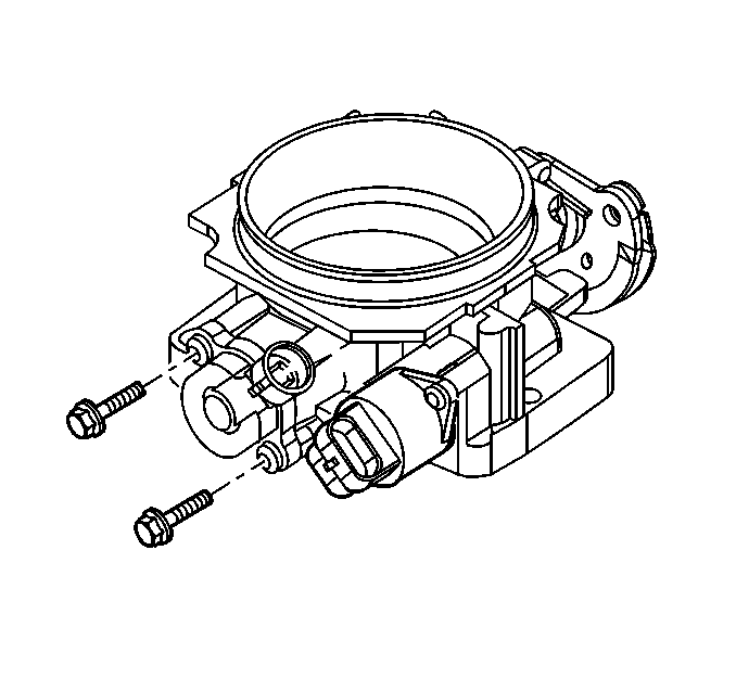
- Remove the mounting screws from the TP sensor.
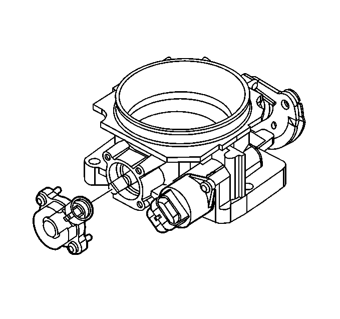
- Remove the TP sensor from the throttle body assembly.
Caution: Unless directed otherwise, the ignition and start switch must be in the OFF or LOCK position, and all electrical loads must be OFF before servicing any electrical component. Disconnect the negative battery cable to prevent an electrical spark should a tool or equipment come in contact with an exposed electrical terminal. Failure to follow these precautions may result in personal injury and/or damage to the vehicle or its components.
Notice: The TP sensor is an electrical component. Do not soak the TP sensor in any liquid cleaner or solvent as damage may result.
Installation Procedure
- Place the TP sensor over the throttle shaft and align the TP mounting holes with their corresponding holes in the throttle body assembly.
- Install the TP sensor mounting screws.
- Install the throttle body. Refer to Throttle Body Assembly Replacement .
- Connect the TP sensor harness connector.
- Install the air cleaner outlet duct.
- Tighten the air cleaner outlet duct wing nut.
- Secure the air cleaner outlet duct to the MAF sensor.
- Connect the breather tube to the air cleaner outlet duct.
- Connect the IAT sensor harness connector.
- Connect the negative battery cable.
Important: Make sure the throttle valve is closed during installation.
Notice: Use the correct fastener in the correct location. Replacement fasteners must be the correct part number for that application. Fasteners requiring replacement or fasteners requiring the use of thread locking compound or sealant are identified in the service procedure. Do not use paints, lubricants, or corrosion inhibitors on fasteners or fastener joint surfaces unless specified. These coatings affect fastener torque and joint clamping force and may damage the fastener. Use the correct tightening sequence and specifications when installing fasteners in order to avoid damage to parts and systems.
Important: The screws used to attach the TP sensor are coated with thread locking adhesive. Clean the attaching screw threads and apply thread locking material GM P/N 1052624 or equivalent.
Tighten
Tighten the screws to 2.0 N·m (18 lb in).
Tighten
Tighten the air cleaner outlet duct clamp to 4 N·m (35 lb in)
.
