Rear Floor Panel Carpet Replacement TrailBlazer EXT, Envoy XL
Removal Procedure
- Remove the front seats. Refer to Front Seat Replacement - Bucket in Seats.
- Remove the second row rear seats. Refer to Rear Seat Replacement in Seats.
- Remove the third row rear seats. Refer to Rear Number 2 Seat Replacement in Seats.
- Remove the front door sill plates. Refer to Front Side Door Sill Plate Replacement .
- Remove the rear door sill plates. Refer to Rear Side Door Sill Plate Replacement .
- Remove the center pillar trim panels. Refer to Center Pillar Garnish Molding Replacement .
- Remove the lift gate door sill plate. Refer to Liftgate Door Sill Plate Replacement .
- Remove the left/right front body side window garnish molding. Refer to Body Side Rear Window Garnish Molding Replacement .
- Remove the left/right rear body side window garnish molding. Refer to Body Side Window Rear Garnish Molding Replacement .
- Remove the bolts from the cargo tie-down loops.
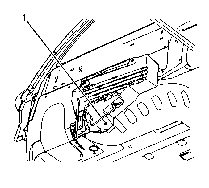
- Remove the nut (1), securing the stowage jack carrier to the wheelhouse panel.
- Loosen the three bolts that secure the jack carrier to the vehicle.
- Remove the carpet from around the wheel stud.
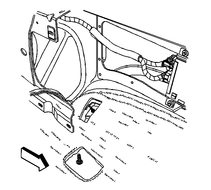
- Remove the body electrical block. Refer to Rear Electrical Center or Junction Block Replacement in Wiring Systems.
- Remove the body electrical block electrical connectors back through the hole in the carpet.
- Pull the communication interface module electrical connectors back through the hole in the carpet.
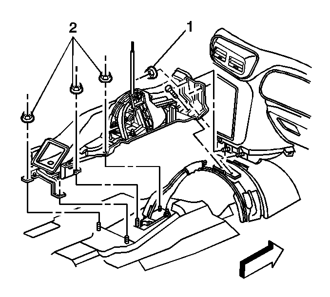
- Remove the floor console to the floor console carrier. Refer to Console Replacement in Instrument Panel, Gages and Console.
- Remove the 4 nuts (2) retaining the rear of the floor console bracket to the floor weld studs.
- Raise the rear portion of the floor console bracket and remove the carpet from underneath the console bracket.
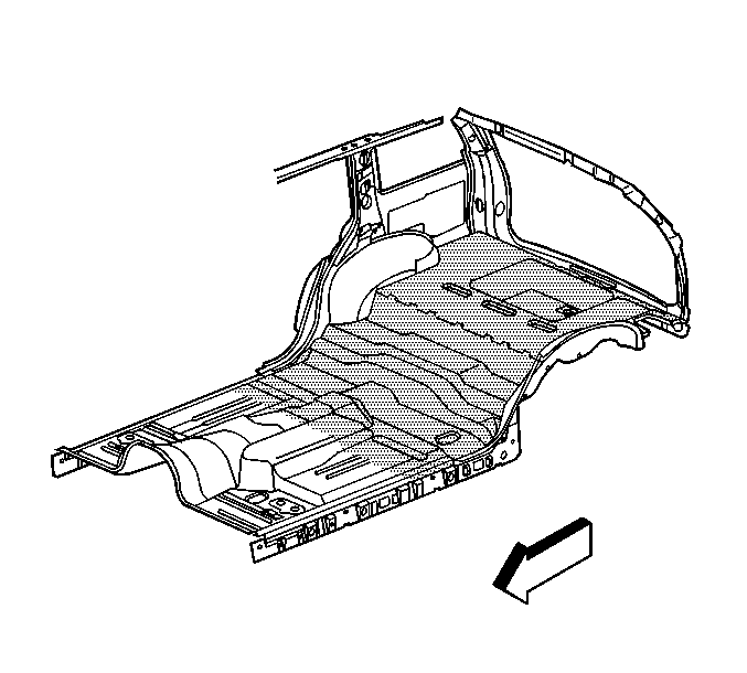
- Remove the carpet from the vehicle.
Notice: Remove the headliner and the headliner harness as an assembly. Do NOT cut or splice the headliner harness. Cutting or splicing the harness may damage the coax cable, resulting in poor radio performance.
Installation Procedure
- Position the carpet to the floor panel.
- Raise the rear portion of the floor console bracket and slide the carpet underneath the console bracket.
- Position the rear carpet over the edge of the front carpet.
- Align the holes in the carpet to the seat studs on the floor panel.
- Install the four nuts (2) retaining the rear of the floor console bracket to the floor weld studs.
- Feed the bussed electrical center base and the communication interface module electrical connectors through the pass through holes in the carpet.
- Install the floor console. Refer to Console Replacement in Instrument Panel, Gages and Console.
- Install the center pillar trim panels. Refer to Center Pillar Garnish Molding Replacement .
- Install the front side door sill plates. Refer to Front Side Door Sill Plate Replacement .
- Pass the communication interface module electrical connectors through the small hole in the carpet.
- Pass the body electrical block electrical connectors through the small hole in the carpet.
- Install the body electrical block. Refer to Rear Electrical Center or Junction Block Replacement in Wiring Systems.
- Install the carpet ensuring that the carpet hooks over the left wheelhouse panel stud.
- Install the nut (1) securing the stowage jack carrier to the wheelhouse panel.
- Install the right rear quarter lower trim panel. Refer to Rear Quarter Trim Panel Replacement - Right Side .
- Install the left rear quarter lower trim panel. Refer to Rear Quarter Trim Panel Replacement - Left Side .
- Install the left/right rear body side trim rear window garnish molding. Refer to Body Side Window Rear Garnish Molding Replacement .
- Install the left/right front body side window garnish molding. Refer to Body Side Rear Window Garnish Molding Replacement .
- Install the lift gate door sill plate. Refer to Liftgate Door Sill Plate Replacement .
- Install the cargo tie-down loops and secure the loops with the tie-down bolts.
- Install the rear side door sill plates. Refer to Rear Side Door Sill Plate Replacement .
- Install the second row seats. Refer to Rear Seat Replacement in Seats.
- Install the third row seats. Refer to Rear Number 2 Seat Replacement in Seats.
- Install the luggage/cargo shade assembly, if equipped.
- Install the cargo net, if equipped.
- Install the front seats. Refer to Front Seat Replacement - Bucket in Seats.
Caution: In order to avoid personal injury or vehicle damage when you repair or replace the carpet, use the same thickness and material size as the original installation. Always return the carpet to the original location.
Notice: Use the correct fastener in the correct location. Replacement fasteners must be the correct part number for that application. Fasteners requiring replacement or fasteners requiring the use of thread locking compound or sealant are identified in the service procedure. Do not use paints, lubricants, or corrosion inhibitors on fasteners or fastener joint surfaces unless specified. These coatings affect fastener torque and joint clamping force and may damage the fastener. Use the correct tightening sequence and specifications when installing fasteners in order to avoid damage to parts and systems.
Tighten
Tighten the nuts to 25 N·m (18 lb ft).
Tighten
Tighten the bolts to 35 N·m (26 lb ft).
Rear Floor Panel Carpet Replacement TrailBlazer, Envoy, Rainier
Removal Procedure
- Remove the front seats. Refer to Front Seat Replacement - Bucket .
- Remove the rear seat cushions. Refer to Rear Seat Cushion Replacement .
- Remove the communication interface module. Refer to Communication Interface Module Replacement .
- Remove the navigation control processor bracket. Refer to Navigation Control Processor Bracket Replacement .
- Remove the seat back, left and right side. Refer to Rear Seat Number 1 Back Replacement .
- Remove the front bucket seats. Refer to Front Seat Replacement - Bucket .
- Remove the front door sill plates. Refer to Front Side Door Sill Plate Replacement .
- Remove the rear door sill plates. Refer to Rear Side Door Sill Plate Replacement .
- Remove the liftgate door sill plate. Refer to Liftgate Door Sill Plate Replacement .
- Remove the center pillar trim panels. Refer to Center Pillar Garnish Molding Replacement .
- Remove the lower rear quarter trim panels. Refer to Rear Quarter Trim Panel Replacement - Left Side or to Rear Quarter Trim Panel Replacement - Right Side .
- Remove the tool kit carrier.
- Remove the bussed electrical center junction block from the bussed electrical center (BEC) base, and the bussed electrical center base from the floor panel studs. Refer to Rear Electrical Center or Junction Block Replacement .
- Remove the child restraint tether anchors. Refer to Child Restraint Tether Anchor Replacement - Rear No. 1 .
- Remove the bussed electrical center base and communication interface module electrical connectors through the pass through holes in the carpet.
- Remove the floor console to the floor console carrier. Refer to Console Replacement .
- Remove the 4 nuts (1, 2) retaining the rear of the floor console bracket to the floor weld studs.
- Raise the rear portion of the floor console bracket and remove the carpet from underneath the console bracket.
- Remove the carpet from the vehicle.
Installation Procedure
- Position the carpet to the floor panel.
- Raise the rear portion of the floor console bracket and slide the carpet underneath the console bracket.
- Position the rear carpet over the edge of the front carpet.
- Align the holes in the carpet to the seat studs on the floor panel.
- Install the 4 nuts retaining the rear of the floor console bracket to the floor weld studs.
- Feed the BEC base and the communication interface module electrical connectors through the pass through holes in the carpet.
- Install the floor console Refer to Console Replacement .
- Install the child restraint tether anchors. Refer to Child Restraint Tether Anchor Replacement - Rear No. 1 .
- Install the BEC. Refer to Rear Electrical Center or Junction Block Replacement .
- Install the tool kit carrier.
- Install the 3 tool carrier nuts to the floor studs.
- Install the lower rear quarter trim panels. Refer to Rear Quarter Trim Panel Replacement - Left Side or to Rear Quarter Trim Panel Replacement - Right Side .
- Install the center pillar trim panels. Refer to Center Pillar Garnish Molding Replacement .
- Install the liftgate door sill plate. Refer to Liftgate Door Sill Plate Replacement .
- Install the rear door sill plates. Refer to Rear Side Door Sill Plate Replacement .
- Install the front door sill plates. Refer to Front Side Door Sill Plate Replacement .
- Install the front bucket seats. Refer to Front Seat Replacement - Bucket .
- Instal the seat back, right and left side. Refer to Rear Seat Number 1 Back Replacement .
- Install the navigation control processor bracket to the floor panel. Refer to Navigation Control Processor Bracket Replacement .
- Install the rear seat cushions. Refer to Rear Seat Cushion Replacement .
- Install the communication interface module. Refer to Communication Interface Module Replacement .
- Install the front seats. Refer to Front Seat Replacement - Bucket .
Caution: In order to avoid personal injury or vehicle damage when you repair or replace the carpet, use the same thickness and material size as the original installation. Always return the carpet to the original location.
Notice: Refer to Fastener Notice in the Preface section.
Tighten
Tighten the nuts to 25 N·m (18 lb ft).
Tighten
Tighten the nuts to 7 N·m (62 lb in).
