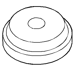
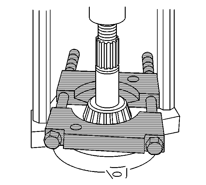
- Install the outer pinion bearing cup.
| • | For vehicles equipped with the 8.0 inch axle, use the
J 7817
(1). |
| • | For vehicles equipped with the 8.6 inch axle, use the
J 8611-01
(1) |
| • | For vehicles equipped with the 9.5 LD inch axle, use the
J 7818
(1). |
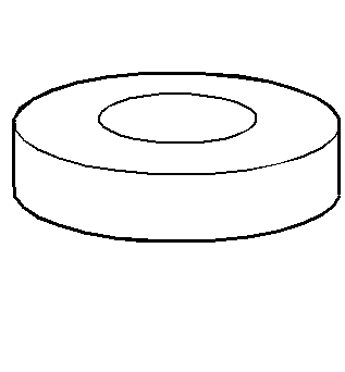
| • | For vehicles with the 8.0/8.6 inch axles or the 9.5 LD inch axle, use the
J 8092
(2). |
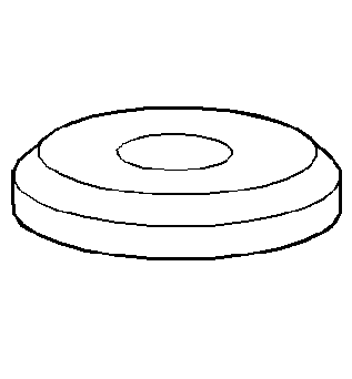
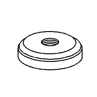
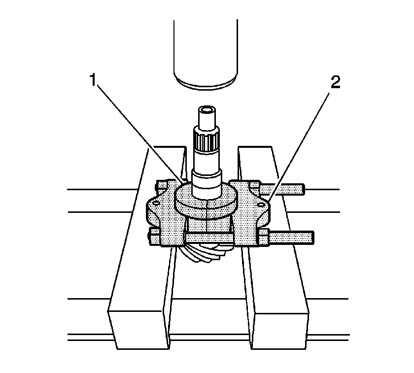
- Install the inner pinion bearing cup using the
J 8608
(2) and the
J 8092
(1).
| • | For vehicles equipped with the 8.0/8.6 inch axle ,
J 8608
(1). |
| • | For vehicles equipped with the 9.5 LD inch axle,
J 22306
(1). |
| • | For vehicles with the 8.0/8.6 inch axles or the 9.5 LD inch axle, use the
J 8092
(2). |
- Determine the selective shim thickness for the pinion. Refer to
Pinion Depth Adjustment
.
- Install the selective shim between the inner pinion bearing and the shoulder on the gear.
- Using the
J 24433
or the
J 36614
, install the inner pinion bearing.
Press the bearing on until the cone seats on the pinion shim.
- Install a new collapsible spacer.
- Lubricate the pinion bearings with axle lubricant. Use the proper fluid. Refer to
Fluid and Lubricant Recommendations
.
- Install the pinion into the axle housing.
- Install the outer pinion bearing onto the pinion.
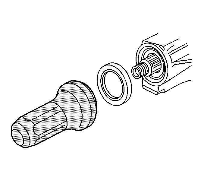
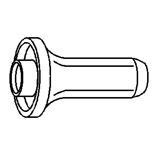
- Install a new pinion oil seal.
| • | For the 8.0 inch axle, use the
J 33782
. |
| • | For the 8.6 inch axle, use the
J 38694
. |
| • | For the 9.5 LD inch axle, use the
J 22388
. |
- Apply sealant GM P/N 12346004 (Canadian P/N 10953480) or equivalent to the splines of the pinion yoke.
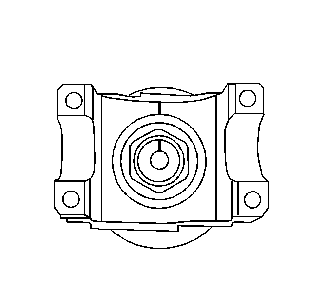
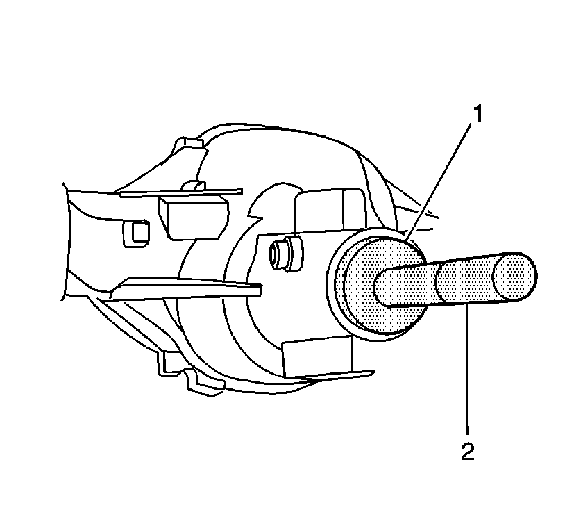
- Install the pinion yoke.
Align the marks made during removal.
- Seat the pinion yoke onto the pinion shaft by tapping it with a soft-faced hammer until a few pinion shaft threads show through the yoke.
- Install the washer and a new pinion nut.
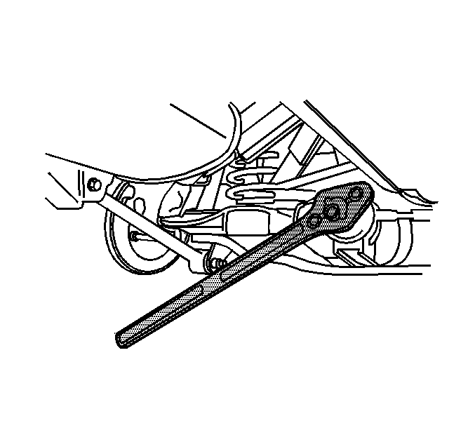
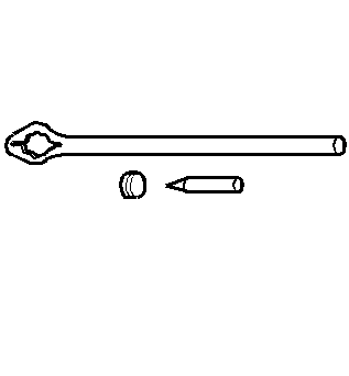
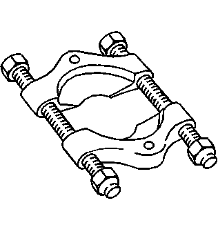
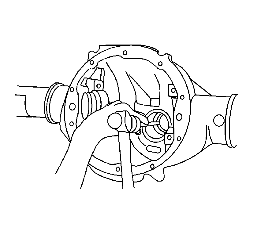
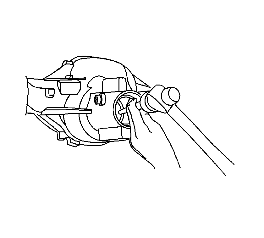
- Install the
J 8614-01
onto the pinion yoke as shown.
Notice: Use the correct fastener in the correct location. Replacement fasteners
must be the correct part number for that application. Fasteners requiring
replacement or fasteners requiring the use of thread locking compound or sealant
are identified in the service procedure. Do not use paints, lubricants, or
corrosion inhibitors on fasteners or fastener joint surfaces unless specified.
These coatings affect fastener torque and joint clamping force and may damage
the fastener. Use the correct tightening sequence and specifications when
installing fasteners in order to avoid damage to parts and systems.
Important: If the rotating torque is exceeded, the pinion will have to be removed and a new collapsible spacer installed.
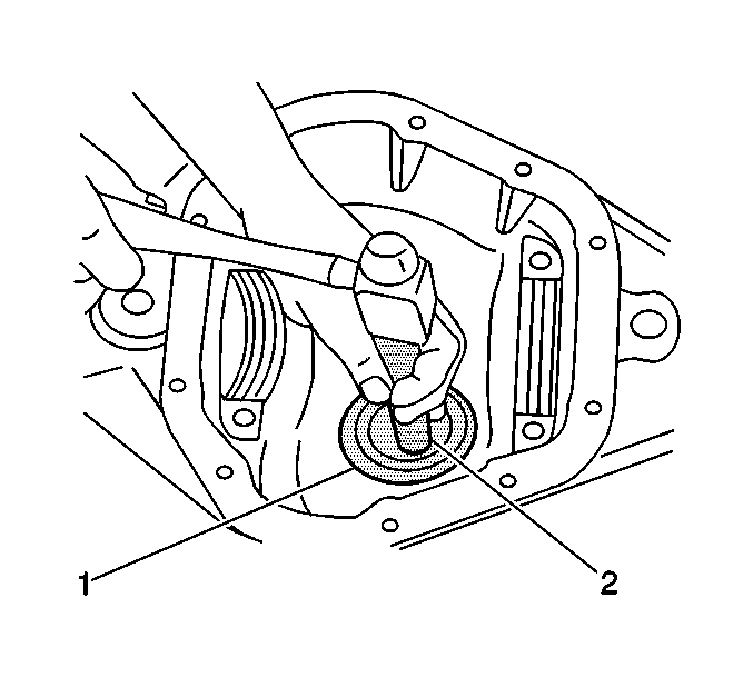
- Tighten the pinion nut while holding the
J 8614-01
.
Tighten
Tighten the pinion nut until the pinion end play is just taken up. Rotate the pinion while tightening the nut to seat the bearings.
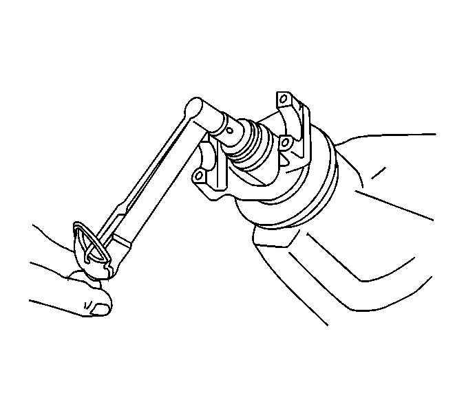
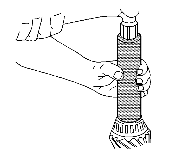
- Measure the rotating torque of the pinion using an inch-pound torque wrench.
Specification
The rotating torque of the pinion should be 1.0-2.3 N·m (10-20 lb in) for used bearings, or 1.7-3.4 N·m (15-30 lb in) for new bearings.
- If the rotating torque measurement is below 1.0 N·m (10 lb in) for used bearings, or 1.7 N·m (15 lb in) for new bearings, continue to tighten the pinion nut.
Tighten
Tighten the pinion nut, in small increments, as needed, until the torque required in order to rotate the pinion is 1.0-2.3 N·m (10-20 lb in) for used bearings, or 1.7-3.4 N·m
(15-30 lb in) for new bearings.
- Once the specified torque is obtained, rotate the pinion several times to ensure the bearings have seated.
Recheck the rotating torque and adjust if necessary.
- Install the differential. Refer to
Differential Replacement
.
- Fill the axle with axle lubricant lubricant. Use the proper fluid. Refer to
Front Axle Lubricant Replacement
.
- Lower the vehicle.
