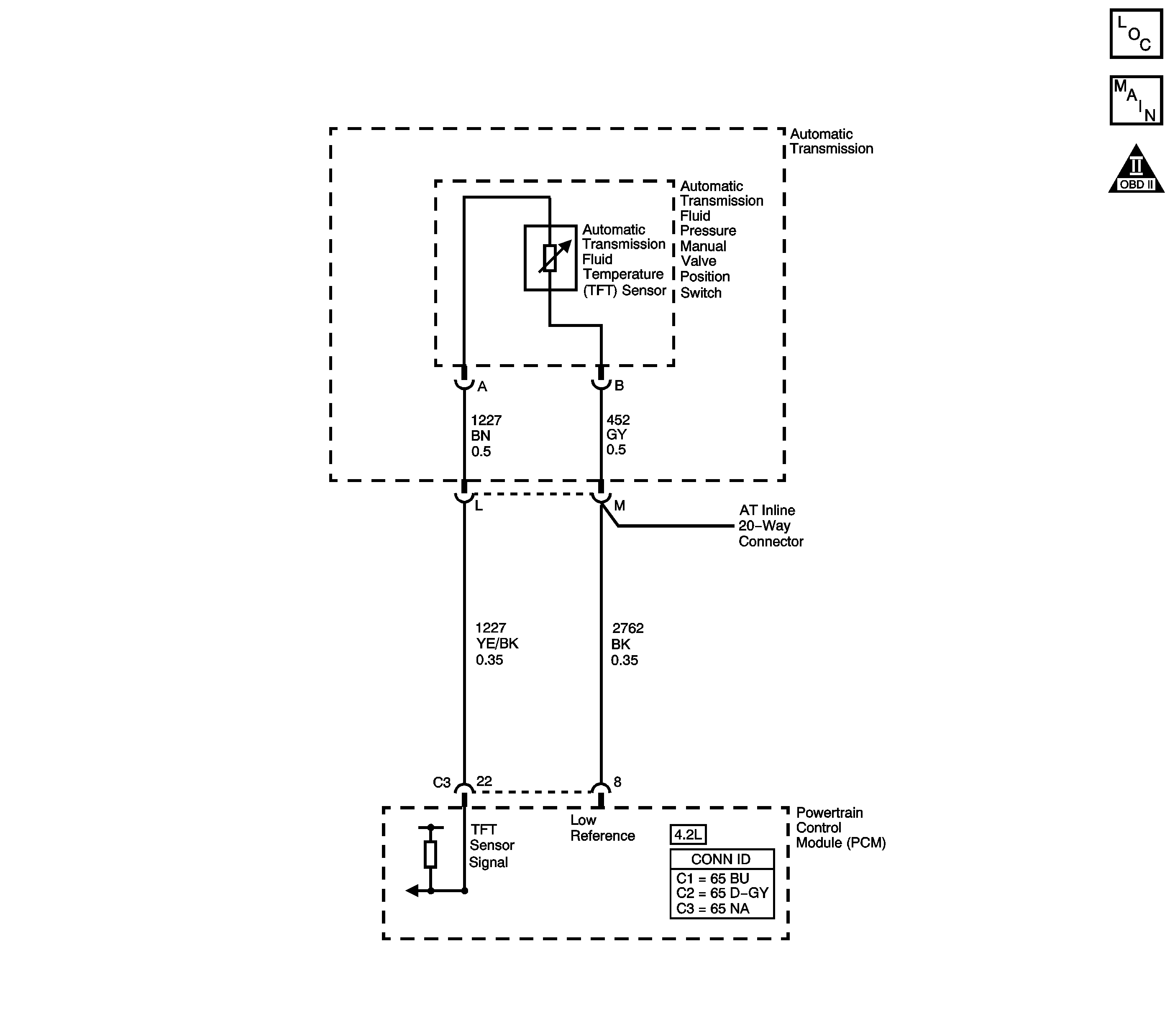
DTC P0713 4.2L
Circuit Description
The automatic transmission fluid temperature (TFT) sensor is part of the automatic transmission fluid pressure (TFP) manual valve position switch. The TFT sensor is a resistor, or thermistor, which changes value based on temperature. The sensor has a negative-temperature coefficient. This means that as the temperature increases, the resistance decreases, and as the temperature decreases, the resistance increases. The powertrain control module (PCM) supplies a 5-volt reference signal to the sensor on the TFT sensor signal circuit and measures the voltage drop in the circuit. When the transmission fluid is cold, the sensor resistance is high and the PCM detects high signal voltage. As the fluid temperature warms to a normal operating temperature, the resistance becomes less and the signal voltage decreases. The PCM uses this information to control shift quality and torque converter clutch apply.
When the PCM detects a continuous open or short to power in the TFT signal circuit or the TFT sensor, then DTC P0713 sets. DTC P0713 is a type C DTC.
Conditions for Running the DTC
| • | The system voltage is 10-18 volts. |
| • | The ignition is ON. |
Conditions for Setting the DTC
The TFT sensor indicates a signal voltage greater than 4.92 volts for 409 seconds (6.8 minutes).
Action Taken When the DTC Sets
| • | The PCM does not illuminate the malfunction indicator lamp (MIL). |
| • | The PCM calculates a default transmission fluid temperature based on engine coolant temperature, intake air temperature and engine run time. |
| • | The PCM freezes transmission adapt functions. |
| • | The PCM records the operating conditions when the Conditions for Setting the DTC are met. The PCM stores this information as Failure Records. |
| • | The PCM stores DTC P0713 in PCM history. |
Conditions for Clearing the DTC
| • | A scan tool can clear the DTC. |
| • | The PCM clears the DTC from PCM history if the vehicle completes 40 warm-up cycles without a non-emission related diagnostic fault occurring. |
| • | The PCM cancels the DTC default actions when the fault no longer exists and the DTC passes. |
Test Description
The numbers below refer to the step numbers on the diagnostic table.
-
This step tests the TFT sensor signal circuit for being shorted to another circuit within the transmission. If the TFT sensor signal circuit shorts to another circuit, which is carrying voltage greater than five volts, the TFT sensor would become open.
-
This step tests the TFT sensor signal circuit for being shorted to voltage, which would be the cause for the open in the TFT sensor.
Step | Action | Value(s) | Yes | No | ||||
|---|---|---|---|---|---|---|---|---|
1 | Did you perform the Diagnostic System Check - Engine Controls? | -- | Go to Step 2 | Go to Diagnostic System Check - Engine Controls in Engine Controls - 4.2L | ||||
2 |
Important: Before clearing the DTC, use the scan tool in order to record the DTC Failure Records. Using the Clear Info function erases the Failure Records from the PCM. Does the scan tool display a Trans. Fluid Temp. less than the specified value? | -39°C (-38°F) | Go to Step 3 | Go to Intermittent Conditions in Engine Controls - 4.2L | ||||
3 |
Refer to Automatic Transmission Inline 20-Way Connector End View . Does the resistance measure less than the specified value? | 100 K ohms | Go to Step 7 | Go to Step 4 | ||||
4 |
Refer to Testing for Continuity in Wiring Systems. Did you find an open condition? | -- | Go to Step 8 | Go to Step 5 | ||||
Measure the resistance between terminal L and all other terminals of the J 44152 . Does the resistance measure less than the specified value? | 1000 ohms | Go to Step 10 | Go to Step 6 | |||||
Test the signal circuit of the TFT sensor for a short to voltage between the PCM connector and the AT inline 20-way connector. Refer to Testing for a Short to Voltage and Wiring Repairs in Wiring Systems. Did you find and correct the condition? | -- | Go to Step 9 | Go to Step 9 | |||||
7 |
Refer to Testing for Continuity and Wiring Repairs in Wiring Systems. Did you find and correct an open condition? | -- | Go to Step 12 | Go to Step 11 | ||||
8 | Replace the automatic transmission wiring harness. Refer to Valve Body and Pressure Switch Replacement . Did you complete the replacement? | -- | Go to Step 12 | -- | ||||
9 | Replace the TFT sensor. Refer to Valve Body and Pressure Switch Replacement . Did you complete the replacement? | -- | Go to Step 12 | -- | ||||
10 |
Refer to Valve Body and Pressure Switch Replacement . Did you complete the replacements? | -- | Go to Step 12 | -- | ||||
11 | Replace the PCM. Refer to Powertrain Control Module Replacement in Engine Controls - 4.2L. Did you complete the replacement? | -- | Go to Step 12 | -- | ||||
12 | Perform the following procedure in order to verify the repair:
Has the test run and passed? | -- | Go to Step 13 | Go to Step 2 | ||||
13 | With the scan tool, observe the stored information, capture info, and DTC Info. Does the scan tool display any DTCs that you have not diagnosed? | -- | Go to Diagnostic Trouble Code (DTC) List in Engine Controls - 4.2L | System OK |
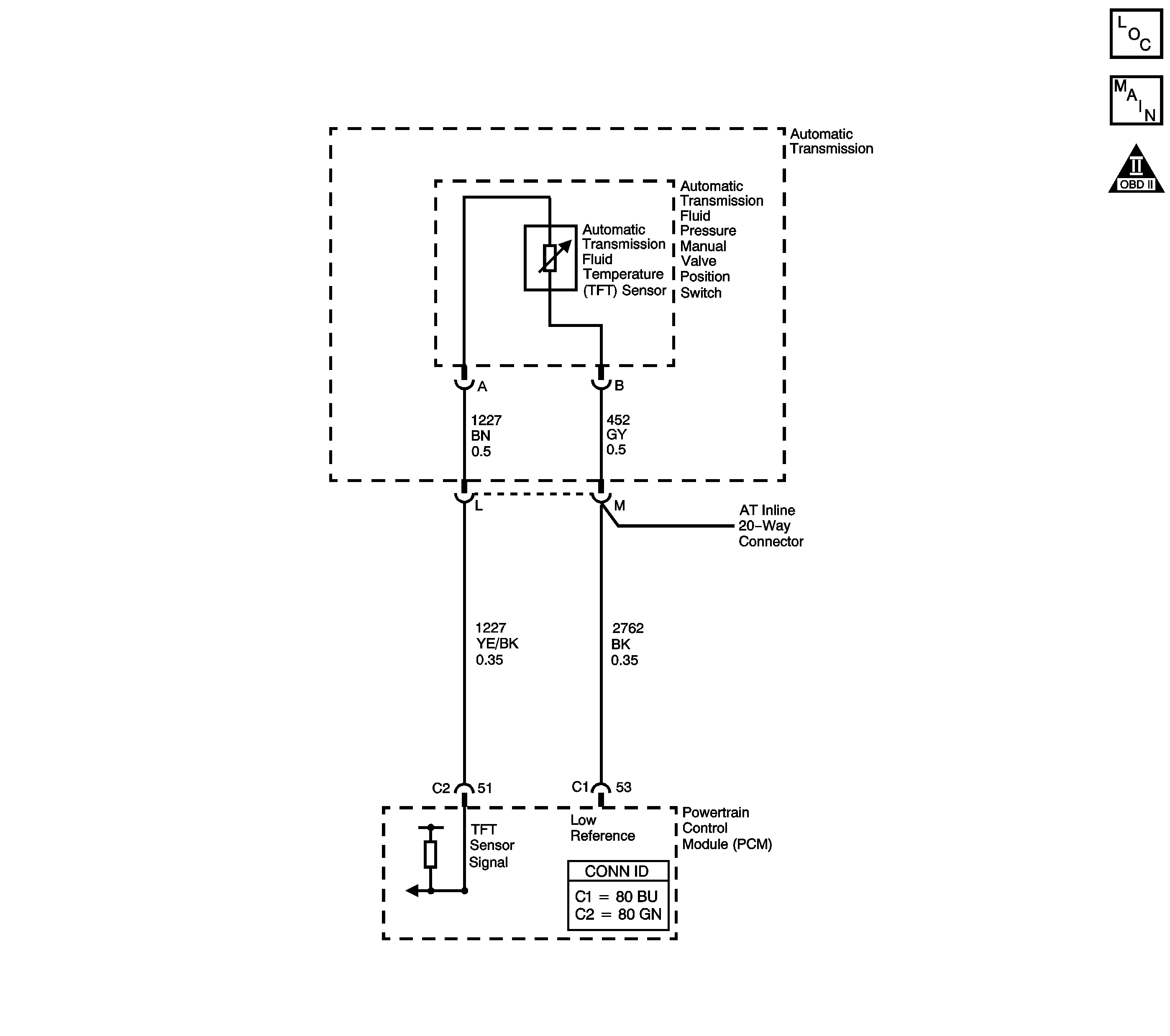
DTC P0713 5.3L
Circuit Description
The automatic transmission fluid temperature (TFT) sensor is part of the automatic transmission fluid pressure (TFP) manual valve position switch. The TFT sensor is a resistor, or thermistor, which changes value based on temperature. The sensor has a negative-temperature coefficient. This means that as the temperature increases, the resistance decreases, and as the temperature decreases, the resistance increases. The powertrain control module (PCM) supplies a 5-volt reference signal to the sensor on the TFT sensor signal circuit and measures the voltage drop in the circuit. When the transmission fluid is cold, the sensor resistance is high and the PCM detects high signal voltage. As the fluid temperature warms to a normal operating temperature, the resistance becomes less and the signal voltage decreases. The PCM uses this information to control shift quality and torque converter clutch apply.
When the PCM detects a continuous open or short to power in the TFT signal circuit or the TFT sensor, then DTC P0713 sets. DTC P0713 is a type C DTC.
Conditions for Running the DTC
| • | The system voltage is 10-18 volts. |
| • | The ignition is ON. |
Conditions for Setting the DTC
The TFT sensor indicates a signal voltage greater than 4.92 volts for 400 seconds (6.8 minutes).
Action Taken When the DTC Sets
| • | The PCM does not illuminate the malfunction indicator lamp (MIL). |
| Important: The actions listed below are in order of highest to lowest priority. |
| • | The PCM determines a default TFT using one of the following: |
| 1. | If any ECT DTCs P0117 or P0118 are set, then the default TFT is equal to 135°C (275°F). |
| 2. | If the ECT is 125°C (257°F) or more, then the default TFT is equal to 135°C (275°F). |
| 3. | If the engine run time is less than 300 seconds and: |
| • | No intake air temperature (IAT) DTCs P0112 or P0113 are set and IAT is available, then the default TFT is equal to IAT. |
| • | Any IAT DTCs P0112 or P0113 are set or IAT is NOT available, then the default TFT is equal to 90°C (194°F). |
| 4. | If the engine run time is greater than 300 seconds and no IAT DTCs P0112 or P0113 are set and IAT is available and ECT is between 40 and 125°C (104 and 257°F) and: |
| • | IAT at startup is less than 15°C (59°F), then the default TFT is equal to the ECT plus 5°C (8°F). |
| • | IAT at startup is greater than 35°C (95°F), then the default TFT is equal to the ECT plus 10°C (16°F). |
| • | IAT at startup is between 15 and 35°C (59 and 95°F), then the default TFT is equal to the ECT. |
| 5. | If the engine run time is greater than 300 seconds and any IAT DTCs P0112 or P0113 are set or IAT is NOT available, then the default TFT is equal to the ECT. |
| 6. | If the engine run time is greater than 300 seconds and ECT is less than 40°C (104°F) or more, then the default TFT is equal to 60°C (140°F). |
| • | The PCM freezes shift adapts from being updated. |
| • | The PCM records the operating conditions when the Conditions for Setting the DTC are met. The PCM stores this information as Failure Records. |
| • | The PCM stores DTC P0713 in PCM history. |
Conditions for Clearing the DTC
| • | A scan tool can clear the DTC. |
| • | The PCM clears the DTC from PCM history if the vehicle completes 40 warm-up cycles without a non-emission-related diagnostic fault occurring. |
| • | The PCM cancels the DTC default actions when the fault no longer exists and/or the ignition switch is OFF long enough in order to power down the PCM. |
Test Description
The numbers below refer to the step numbers on the diagnostic table.
-
This step tests the TFT sensor signal circuit for being shorted to another circuit within the transmission. If the TFT sensor signal circuit shorts to another circuit, which is carrying voltage greater than five volts, the TFT sensor would become open.
-
This step tests the TFT sensor signal circuit for being shorted to voltage, which would be the cause for the open in the TFT sensor.
Step | Action | Value(s) | Yes | No | ||||
|---|---|---|---|---|---|---|---|---|
1 | Did you perform the Diagnostic System Check - Engine Controls? | -- | Go to Step 2 | Go to Diagnostic System Check - Engine Controls in Engine Controls-4.8L, 5.3L and 6.0L | ||||
2 |
Important: Before clearing the DTC, use the scan tool in order to record the DTC Failure Records. Using the Clear Info function erases the Failure Records from the PCM. Does the scan tool display a Trans. Fluid Temp. less than the specified value? | -39°C (-38°F) | Go to Step 3 | Go to Intermittent Conditions in Engine Controls - 4.8L, 5.3L and 6.0L | ||||
3 |
Refer to Automatic Transmission Inline 20-Way Connector End View . Does the resistance measure less than the specified value? | 100 K ohms | Go to Step 7 | Go to Step 4 | ||||
4 |
Refer to Testing for Continuity in Wiring Systems. Did you find an open condition? | -- | Go to Step 8 | Go to Step 5 | ||||
Measure the resistance between terminal L and all other terminals of the J 44152 . Does the resistance measure less than the specified value? | 1000 ohms | Go to Step 10 | Go to Step 6 | |||||
Test the signal circuit of the TFT sensor for a short to voltage between the PCM connector and the AT inline 20-way connector. Refer to Testing for a Short to Voltage and Wiring Repairs in Wiring Systems. Did you find and correct the condition? | -- | Go to Step 9 | Go to Step 9 | |||||
7 |
Refer to Testing for Continuity and Wiring Repairs in Wiring Systems. Did you find and correct an open condition? | -- | Go to Step 12 | Go to Step 11 | ||||
8 | Replace the automatic transmission wiring harness. Refer to Valve Body and Pressure Switch Replacement . Did you complete the replacement? | -- | Go to Step 12 | -- | ||||
9 | Replace the TFT sensor. Refer to Valve Body and Pressure Switch Replacement . Did you complete the replacement? | -- | Go to Step 12 | -- | ||||
10 |
Refer to Valve Body and Pressure Switch Replacement . Did you complete the replacements? | -- | Go to Step 12 | -- | ||||
11 | Replace the PCM. Refer to Powertrain Control Module Replacement in Engine Controls - 4.8L, 5.3L and 6.0L. Did you complete the replacement? | -- | Go to Step 12 | -- | ||||
12 | Perform the following procedure in order to verify the repair:
Has the test run and passed? | -- | Go to Step 13 | Go to Step 2 | ||||
13 | With the scan tool, observe the stored information, capture info, and DTC Info. Does the scan tool display any DTCs that you have not diagnosed? | -- | Go to Diagnostic Trouble Code (DTC) List in Engine Controls - 4.8L, 5.3L and 6.0L | System OK |
