For 1990-2009 cars only
Removal Procedure
Caution: Refer to Propeller Shaft Caution in the Preface section.
- Place transmission in neutral.
- Release the park brake, if applied.
- Raise and support the vehicle. Refer to Lifting and Jacking the Vehicle.
- Rotate the propeller shafts so that all the external clips are aligned.
- Mark the rear propeller shaft to the pinion drive flange, center bearing support, and transmission.
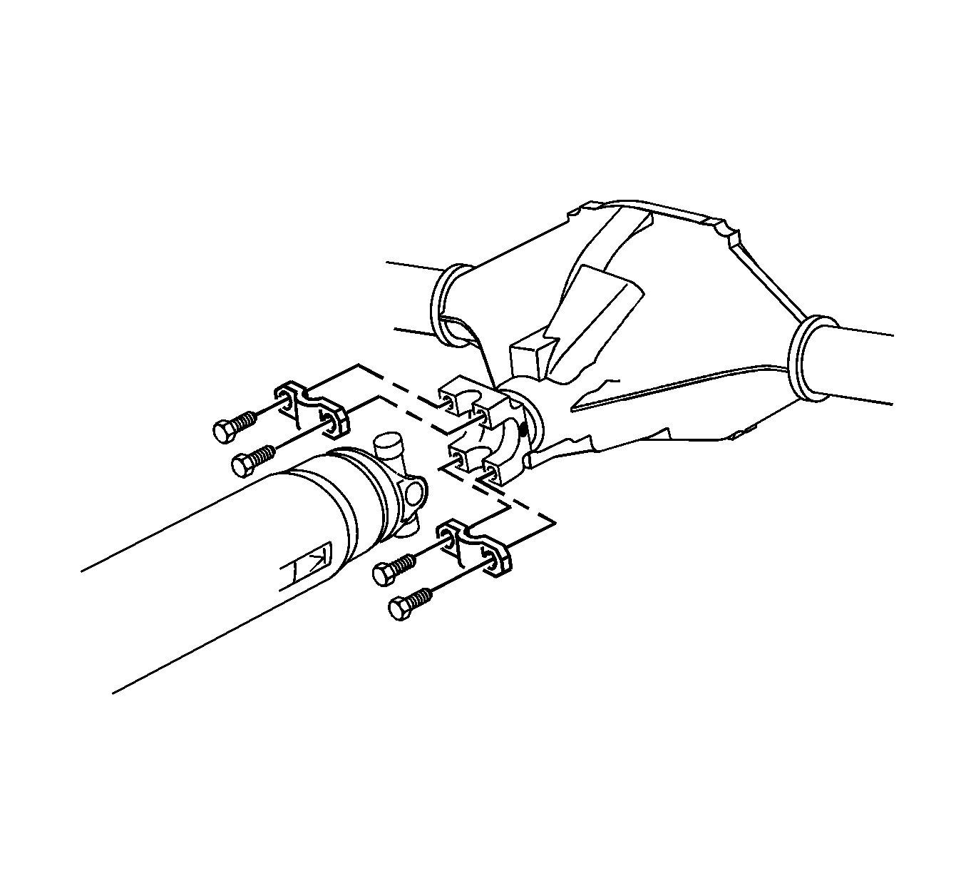
- Remove the clamps and retaining bolts for the rear propeller shaft at the pinion drive flange and the center bearing.
- Using tape or a rubber band, wrap the rear U-Joint bearing caps to ensure that they not separate from the U-Joint.
- Remove the rear propeller shaft from the center bearing.
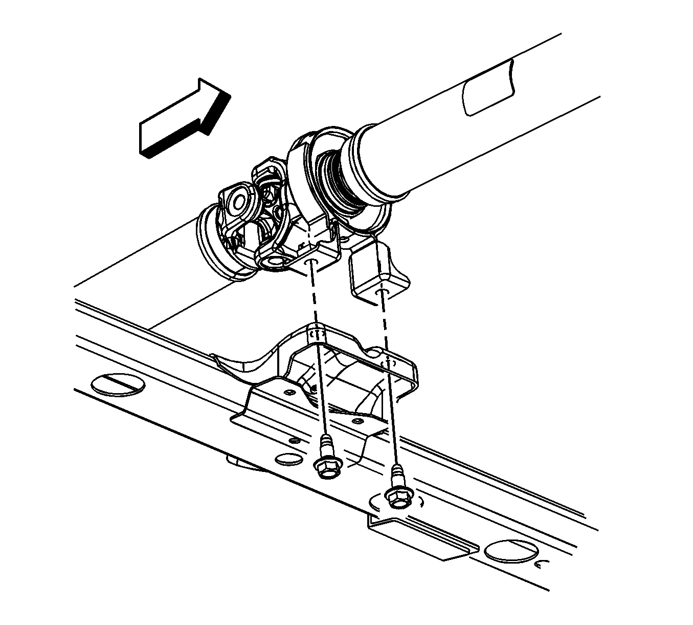
- Remove the mounting bolts for the center bearing.
- Remove the center bearing from the crossmember.
- Remove the propeller shaft from the transmission.
Note: The following service procedure will ensure the proper alignment of all U-Joint to the transmission, center bearing support and the rear drive axle pinion flange.


Installation Procedure
- Align the reference marks on the propeller shaft to the transmission.
- Install the propeller shaft in the transmission.
- Install the center bearing to the crossmember.
- Install the center bearing mounting bolts and tighten to 80 N·m (59 lb ft).
- Rotate the propeller shaft so that the alignment marks and the pinion yoke are in alignment.
- Remove the tape and or rubber band.
- Position the U-Joint in the pinion yoke.
- Install the clamps and retaining bolts and tighten the bolts to 30 N·m (22 lb ft).
- Double check the alignment marks to ensure that they are aligned properly
- Lower the vehicle.
Caution: Refer to Fastener Caution in the Preface section.


