Special Tools
| • | J 44221 Camshaft Holding Tool |
| • | J 44222 Camshaft Sprocket Holding Tool |
| • | J 45059 Angle Meter |
Removal Procedure
- Remove the camshaft cover. Refer to Camshaft Cover Replacement.
- Remove the camshaft position (CMP) sensor. Refer to Camshaft Position Sensor Replacement.
- Rotate the crankshaft in the engine rotational direction clockwise, until the #1 piston is at top dead center (TDC) on the compression stroke.
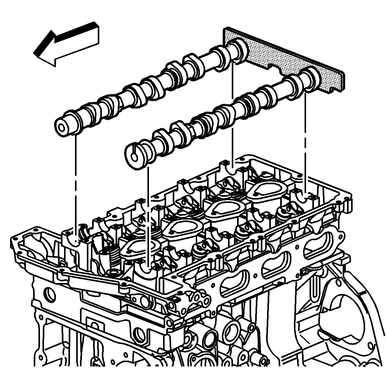
- Install the J 44221 to the rear of the camshafts.
- Remove and discard the intake and the exhaust camshaft sprocket bolts.
- Install the J 44222 onto the cylinder head and adjust the horizontal bolts into the camshaft sprockets in order to maintain chain tension and keep from disturbing the timing chain components.
- Carefully slide the sprockets with the timing chain from the camshafts to the J 44222 .
- Alternately loosen the camshaft cap bolts a few turns at a time until all valve spring pressure has been released.
- Remove the camshaft caps.
- Remove the J 44221 from the camshafts.
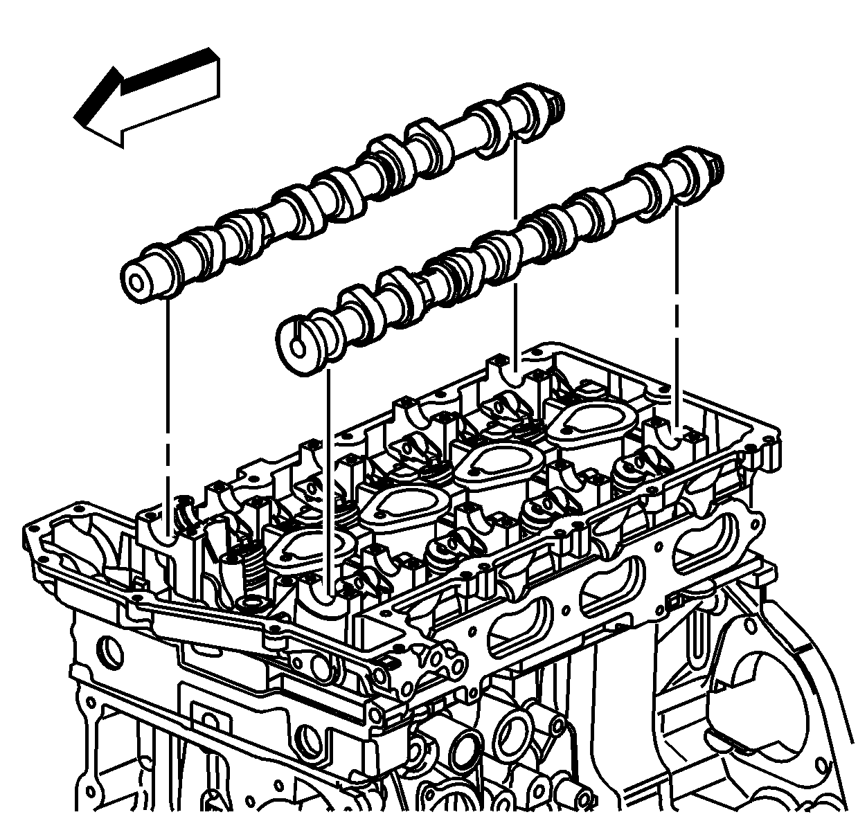
- Remove the camshafts from the cylinder head.
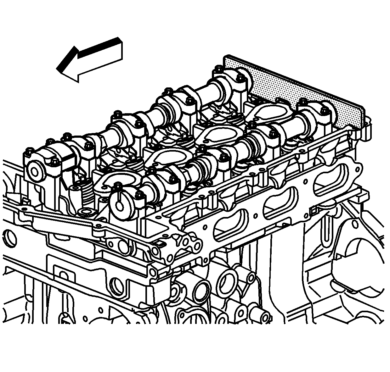
Warning: Refer to Camshaft Holding Tool Warning in the Preface section.
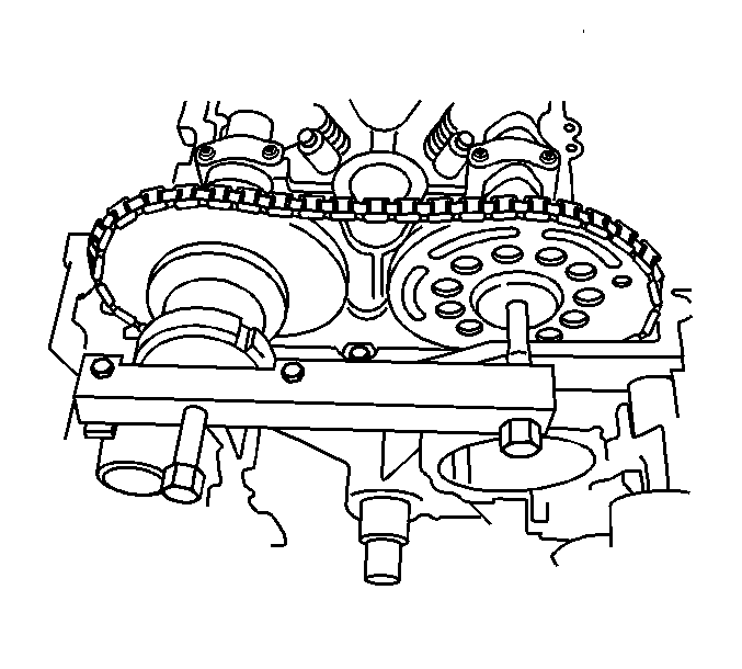
Note: In order to maintain timing chain tension, make sure the 2 bolts that hold J 44222 to the front of the cylinder head are completely tightened and the horizontal bolt into the exhaust camshaft phaser actuator sprocket is adjusted correctly before sliding the sprockets off the camshafts. Failure to do so may disturb the timing chain components.
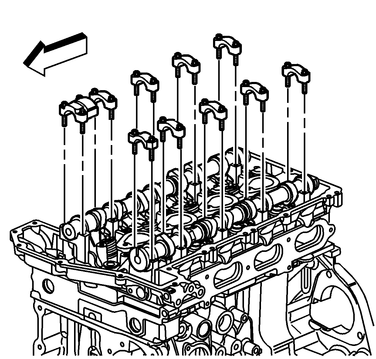
Note: Place the camshaft caps in a rack to ensure the caps are installed in the same location from which they were removed.
Installation Procedure
- Coat the camshaft journals, camshaft journal thrust face, and camshaft lobes with clean engine oil.
- Install the J 44221 with the camshaft flats up and the #1 piston at TDC.
- Install the intake and exhaust camshafts to their original positions.
- Observe the markings on the camshaft caps. Each camshaft cap is marked in order to identify its location. The markings have the following meanings:
- Install the camshaft caps according to the identification marks.
- Install the camshaft cap bolts. Tighten the bolts evenly in order to compress the valve springs before final torque.
- Carefully slide the sprockets with the timing chain from the J 44222 to the camshafts.
- Remove the J 44222 from the cylinder head.
- Install the new intake camshaft sprocket bolt.
- Install the new exhaust camshaft actuator bolt.
- Remove the J 44221 from the camshafts.
- Install the CMP sensor. Refer to Camshaft Position Sensor Replacement.
- Install the camshaft cover. Refer to Camshaft Cover Replacement.
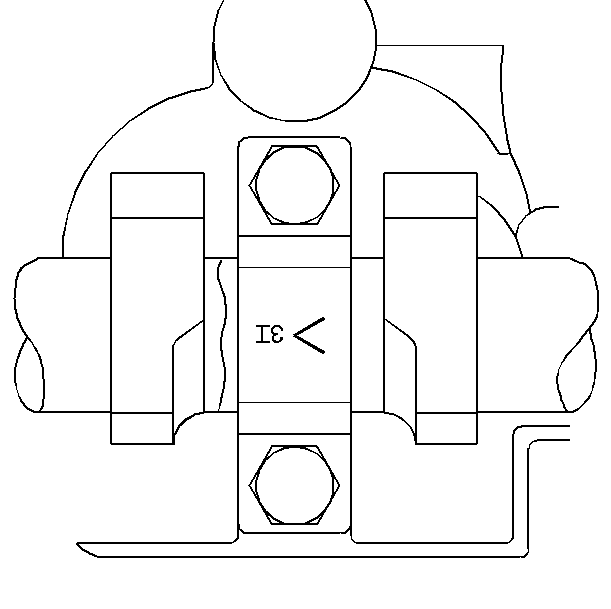
| • | The arrow should point to the front of the engine. |
| • | The number indicates the position from the front of the engine. |
| • | The "E" indicates the exhaust camshaft. |
| • | The "I" indicates the intake camshaft. |

Caution: Refer to Fastener Caution in the Preface section.
Tighten the bolts to 12 N·m (106 lb in).

Note:
• To aid in aligning the sprockets to the camshafts, use a 25 mm (1 in) wrench on the hex of the camshafts to rotate. • Ensure the alignment pins are properly engaged with the camshafts.
| • | Tighten the intake camshaft sprocket bolt to 20 N·m (15 lb ft) plus an additional 100 degrees using the J 45059 . |
| • | Tighten the exhaust camshaft actuator bolt to 25 N·m (18 lb ft) plus an additional 135 degrees using the J 45059 . |

