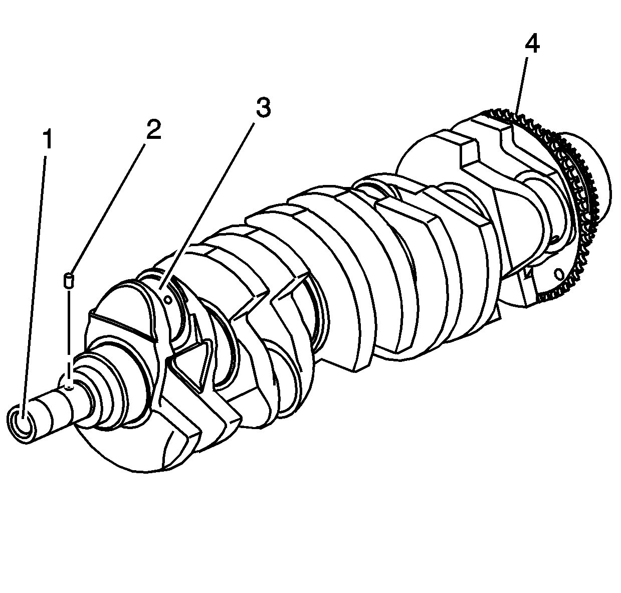
Important: Use care when handling the crankshaft. Avoid damage to the reluctor wheel and crankshaft bearing surfaces.
- Clean the crankshaft of all elements.
- Inspect the crankshaft oil passages for obstructions.
- Inspect the crankshaft for the following conditions:
| • | Worn crankshaft pin (2) |
| • | Wear without any grooves or scratches (3) |
| • | Pitting or embedded bearing material (3) |
| • | Overheating - discoloration (3) |

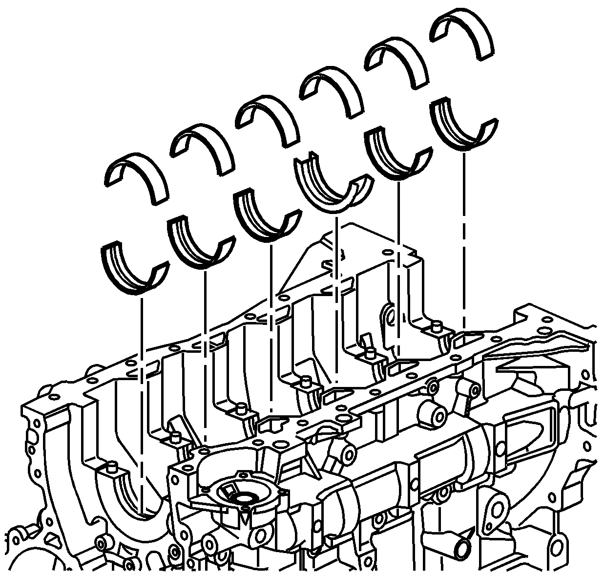
- Inspect the corresponding crankshaft bearing inserts for embedded material and determine
the source of the material.
Important: If cracks, severe gouges or burned spots are found, replace the crankshaft. Remove slight roughness using a fine polishing cloth soaked in clean engine oil. Remove any burrs using a fine oil stone.
- Inspect the outer surfaces of the crankshaft bearings for the following conditions:
| • | Wear -- surface wear indicates either movement of the insert or high spots in the surrounding material (spot wear) |
| • | Overheating or discoloration |
| • | Looseness or rotation indicated by flattened tangs and wear grooves |
Important: Note the location of the crankshaft main bearing high spots. If the spots are not in line, the crankshaft is bent. Replace the crankshaft.
- Inspect the crankshaft main bearings for craters or pockets. Flattened sections on the crankshaft bearing halves also indicate fatigue.
- Inspect the thrust surfaces of the main thrust bearing for the following conditions:
| • | Grooving -- Grooves are caused by irregularities of the crankshaft thrust surface. |
- Inspect the crankshaft bearings for excessive scoring or discoloration.
- Inspect the crankshaft bearings for dirt or imbedded debris.
- Inspect the crankshaft bearings for improper seating indicated by bright, polished sections.
- Inspect the crankshaft bearings for uneven side-to-side wear. This may indicate a bent crankshaft or a tapered bearing journal.
Important: If crankshaft bearing failure is due to conditions other than normal wear, investigate the cause of the condition. Inspect the crankshaft or connecting rod bearing bores.
- Inspect the connecting rod bearing bores using the following procedure:
| 12.1. | Tighten the connecting rod bearing cap to specification. |
| 12.2. | Use
J 8087
to measure the bearing bore for taper and out-of-round. Record the readings. |
| 12.3. | No taper or out-of-round should exist. |

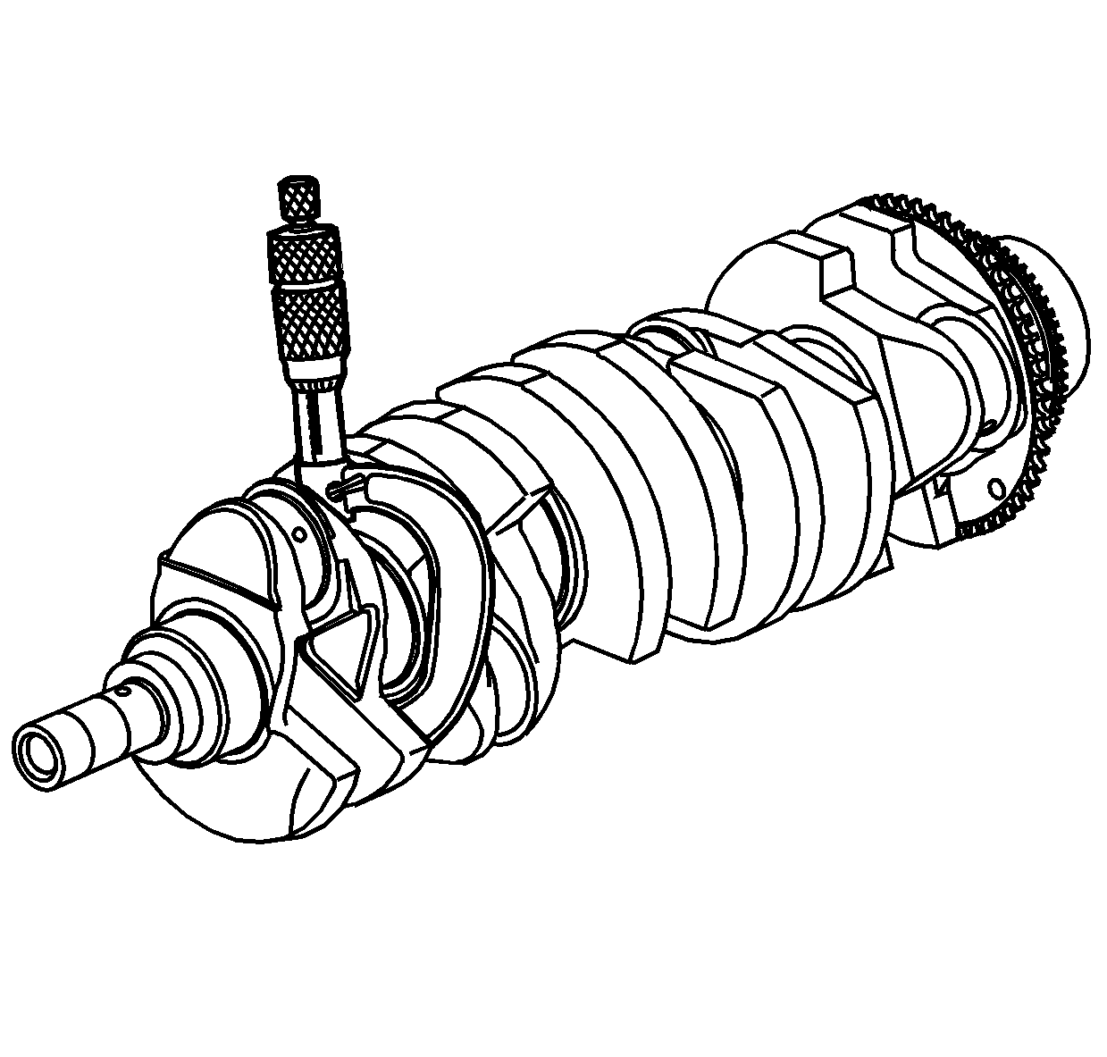
- Measure the crankshaft bearing journal diameter with a
micrometer in several places, 90 degrees apart. Average the measurements.

- Measure the crankshaft bearing journal taper and runout.
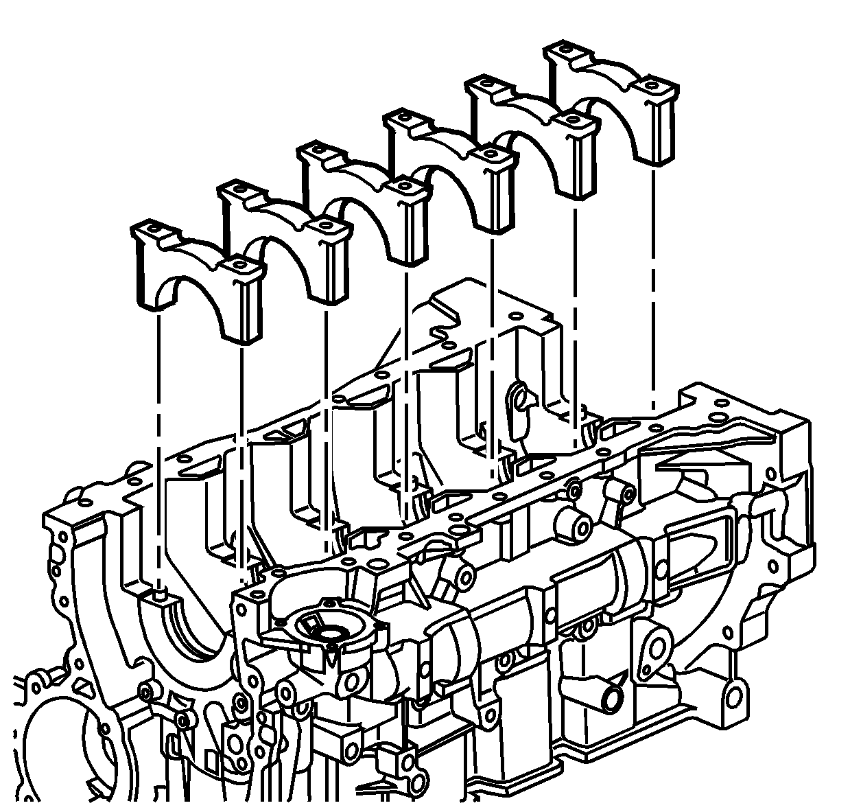
- Install the crankshaft bearing caps.
- Install the crankshaft main bearing cap stiffener.
Notice: Use the correct fastener in the correct location. Replacement fasteners
must be the correct part number for that application. Fasteners requiring
replacement or fasteners requiring the use of thread locking compound or sealant
are identified in the service procedure. Do not use paints, lubricants, or
corrosion inhibitors on fasteners or fastener joint surfaces unless specified.
These coatings affect fastener torque and joint clamping force and may damage
the fastener. Use the correct tightening sequence and specifications when
installing fasteners in order to avoid damage to parts and systems.
- Install the crankshaft bearing cap bolts.
Tighten
- Tighten the crankshaft bearing cap bolts to 25 N·m (18 lb ft).
- Use
J 45059
to tighten the crankshaft bearing cap bolts an additional 180 degrees.
- Measure the crankshaft main bearing inside diameter with an inside micrometer.
- Measure the connecting rod inside diameter in the same direction as the length of the rod with an inside micrometer.
- If the specified clearances cannot be met, the crankshaft, connecting rods, or block may need to be replaced.


