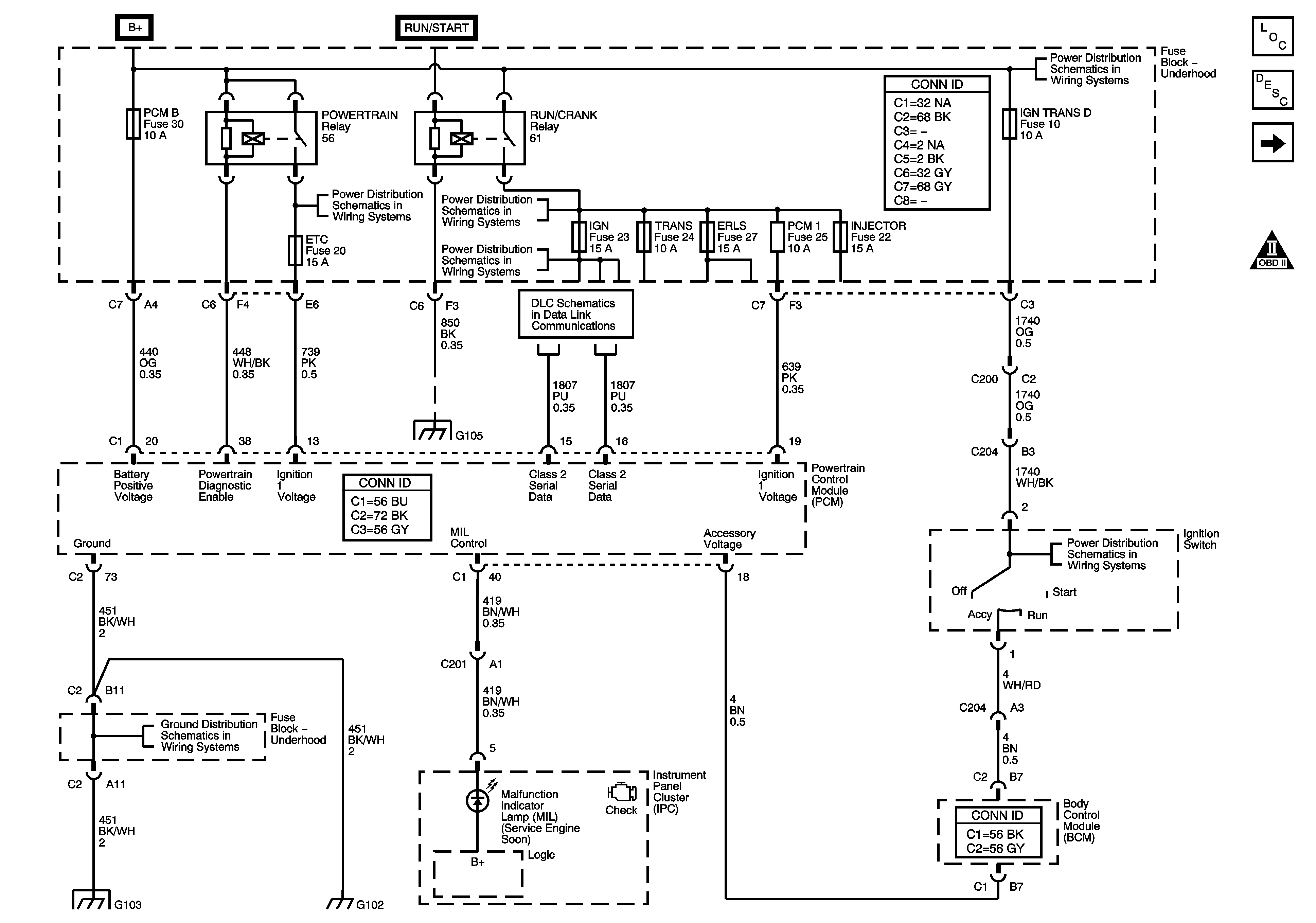
| Figure 1: |
Power, Ground, MIL, and DLC
|
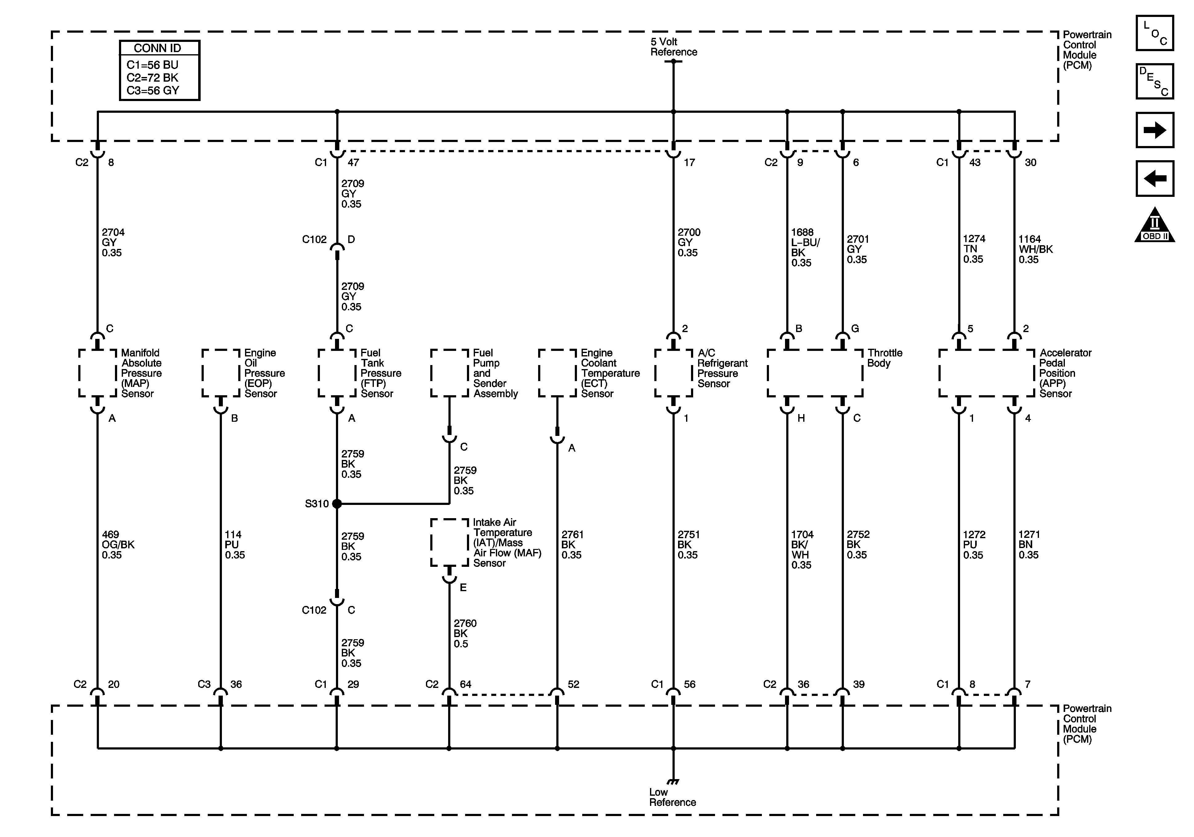
| Figure 2: |
5-Volt Reference
|
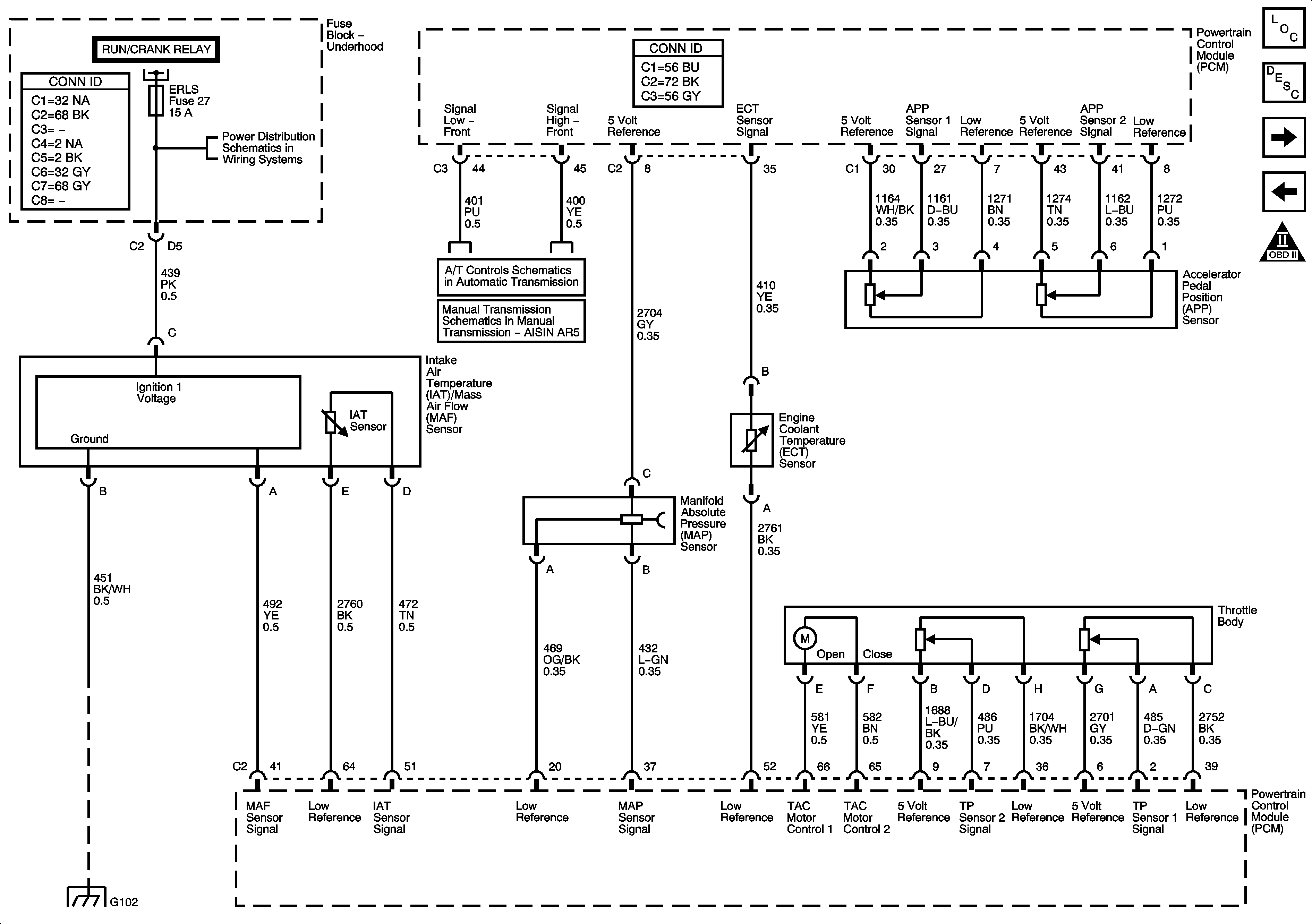
| Figure 3: |
Engine Data Sensors
|
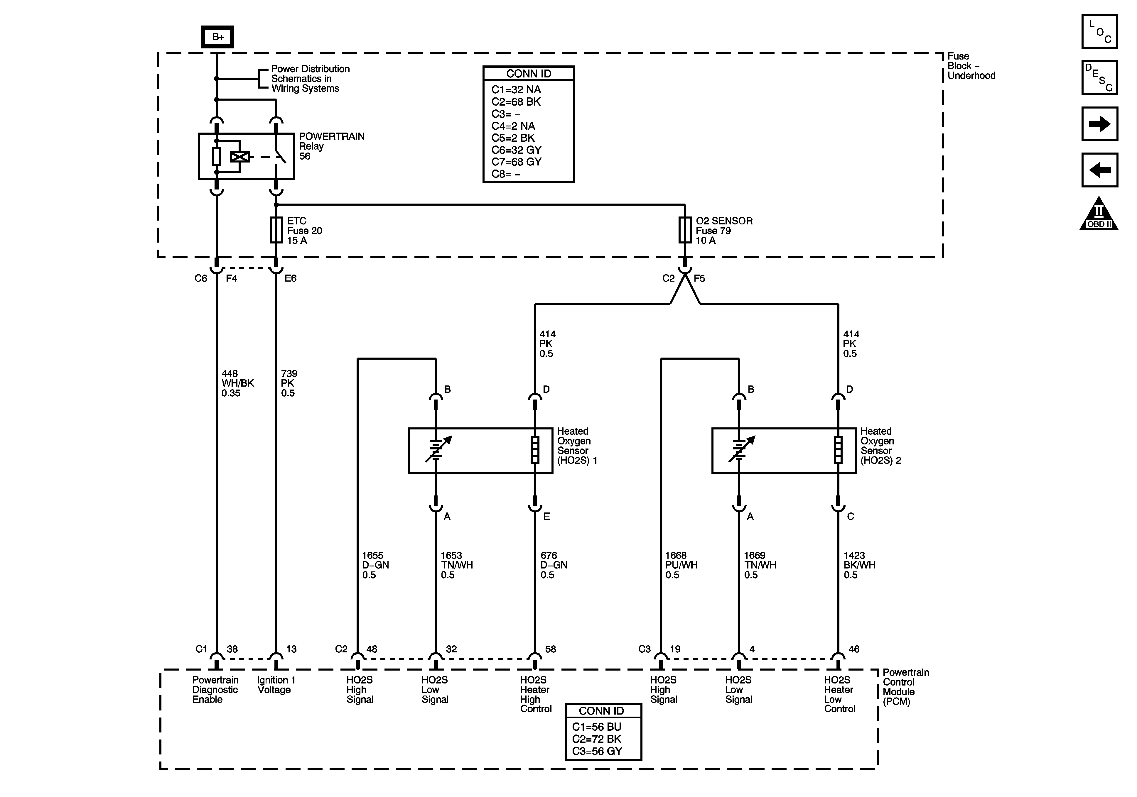
| Figure 4: |
Oxygen Sensors
|
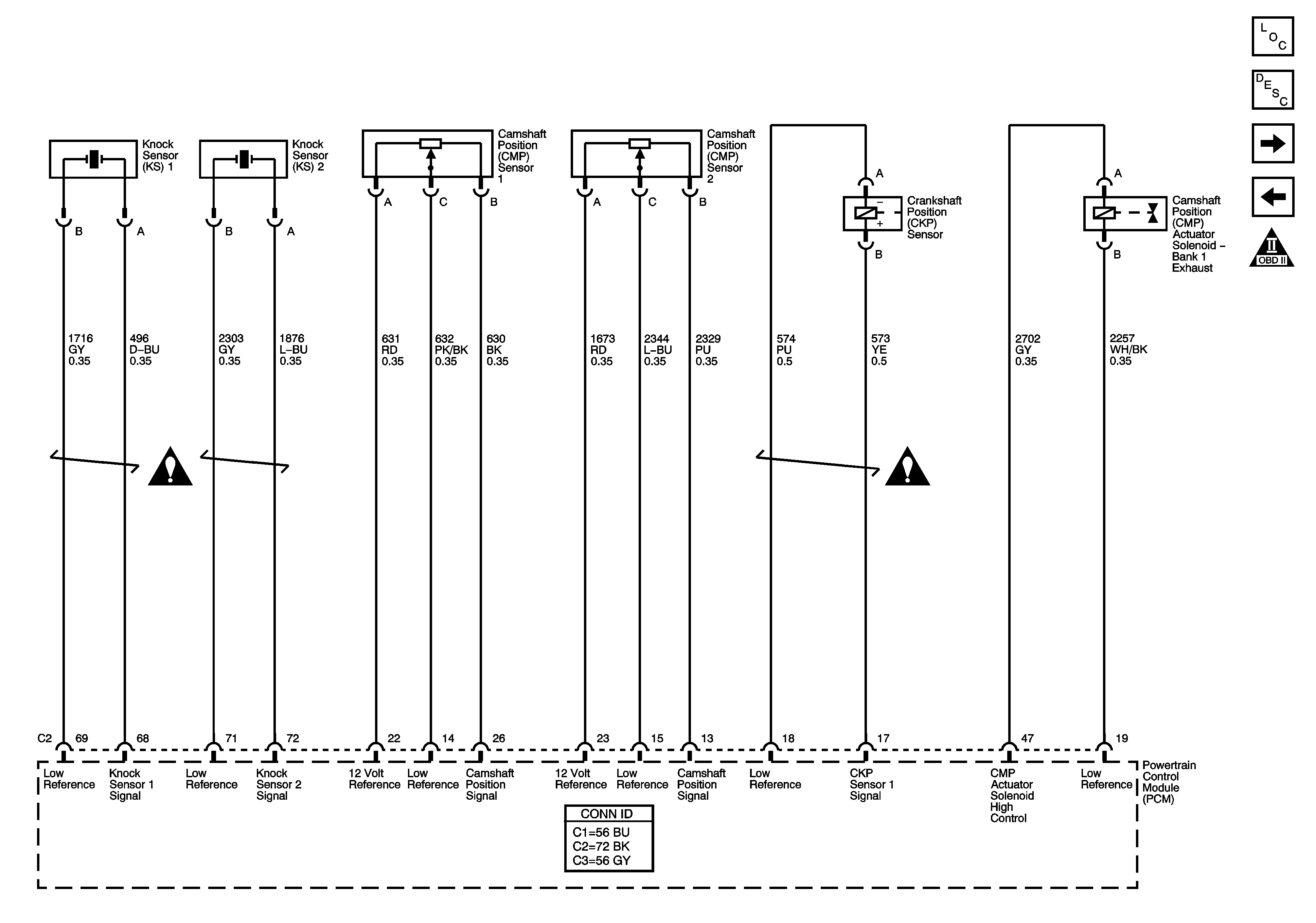
| Figure 5: |
Knock, CMP, CKP Sensors, and CMP Actuator Solenoid
|
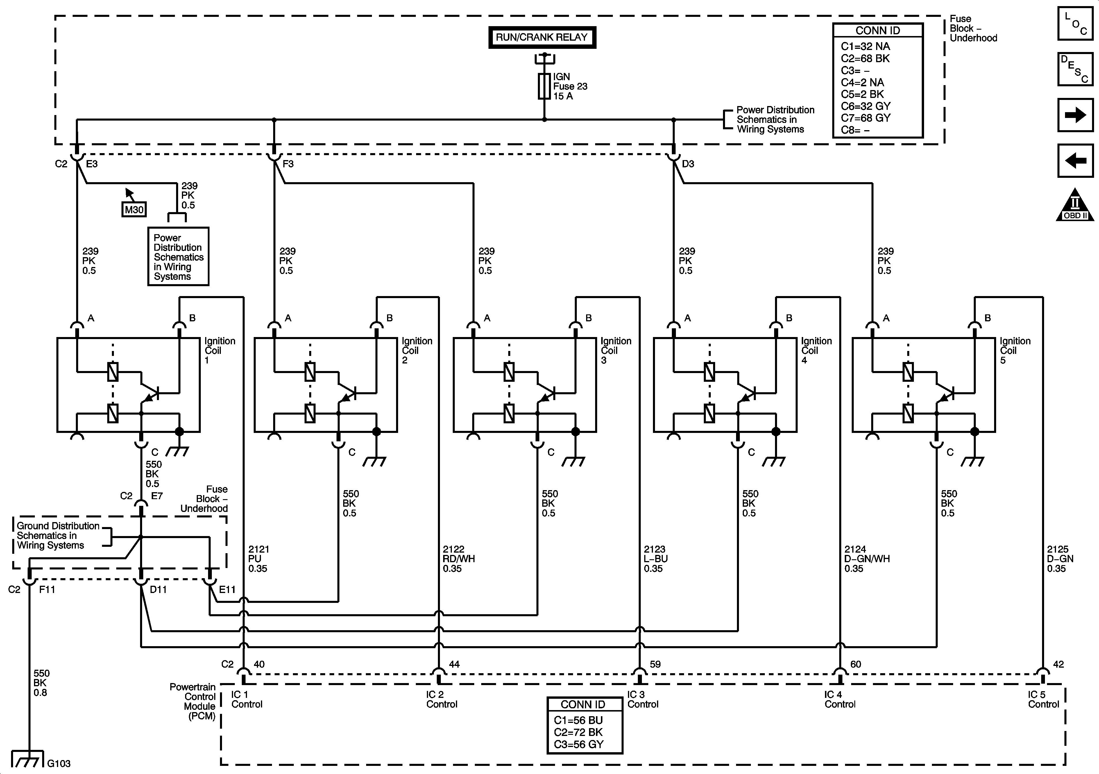
| Figure 6: |
Ignition Controls
|
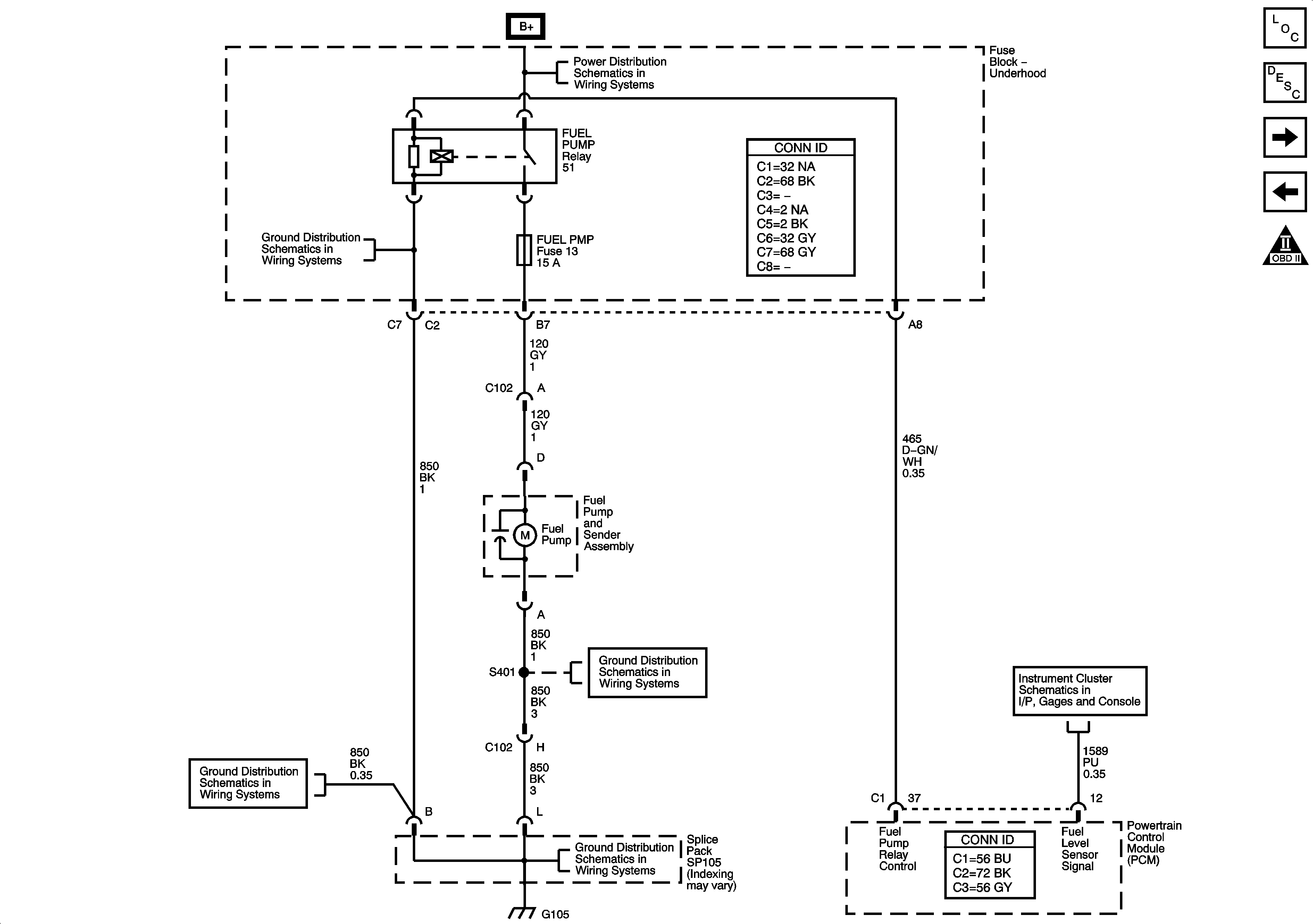
| Figure 7: |
Fuel Controls
|
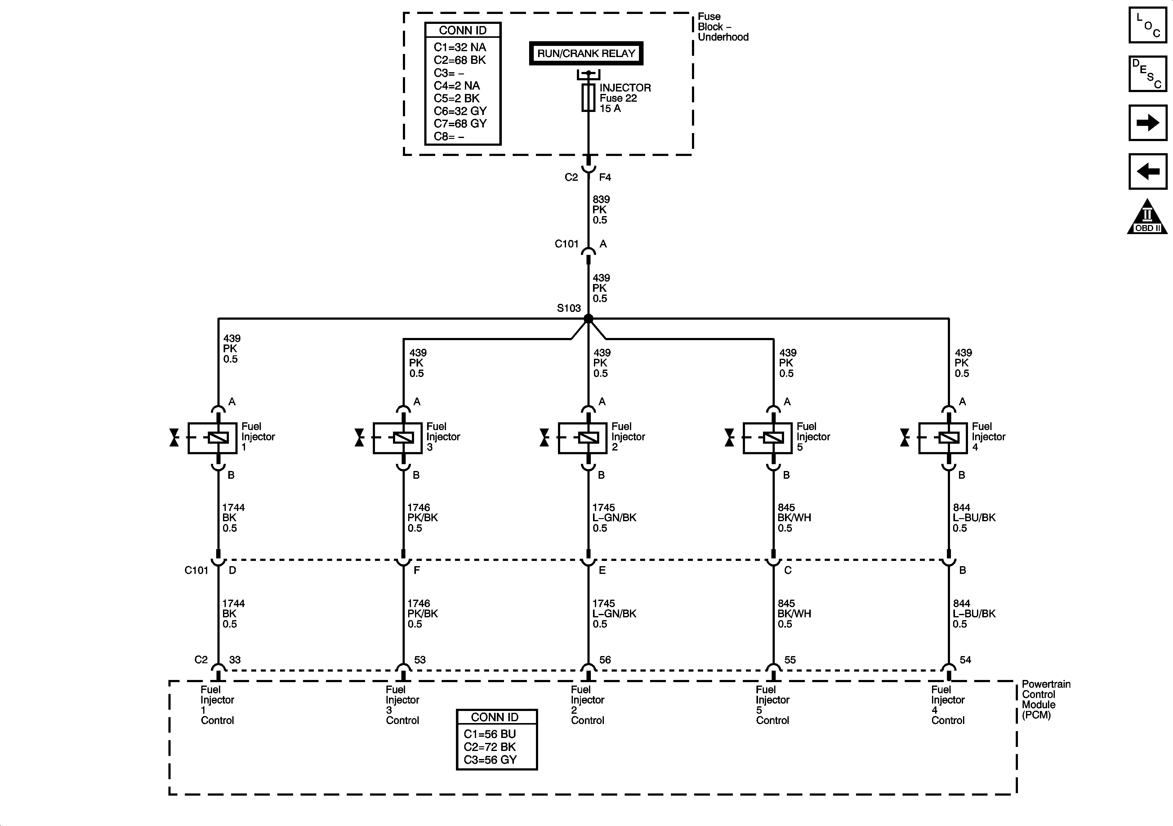
| Figure 8: |
Fuel Injection Controls
|
| Figure 9: |
Fuel and EVAP Controls
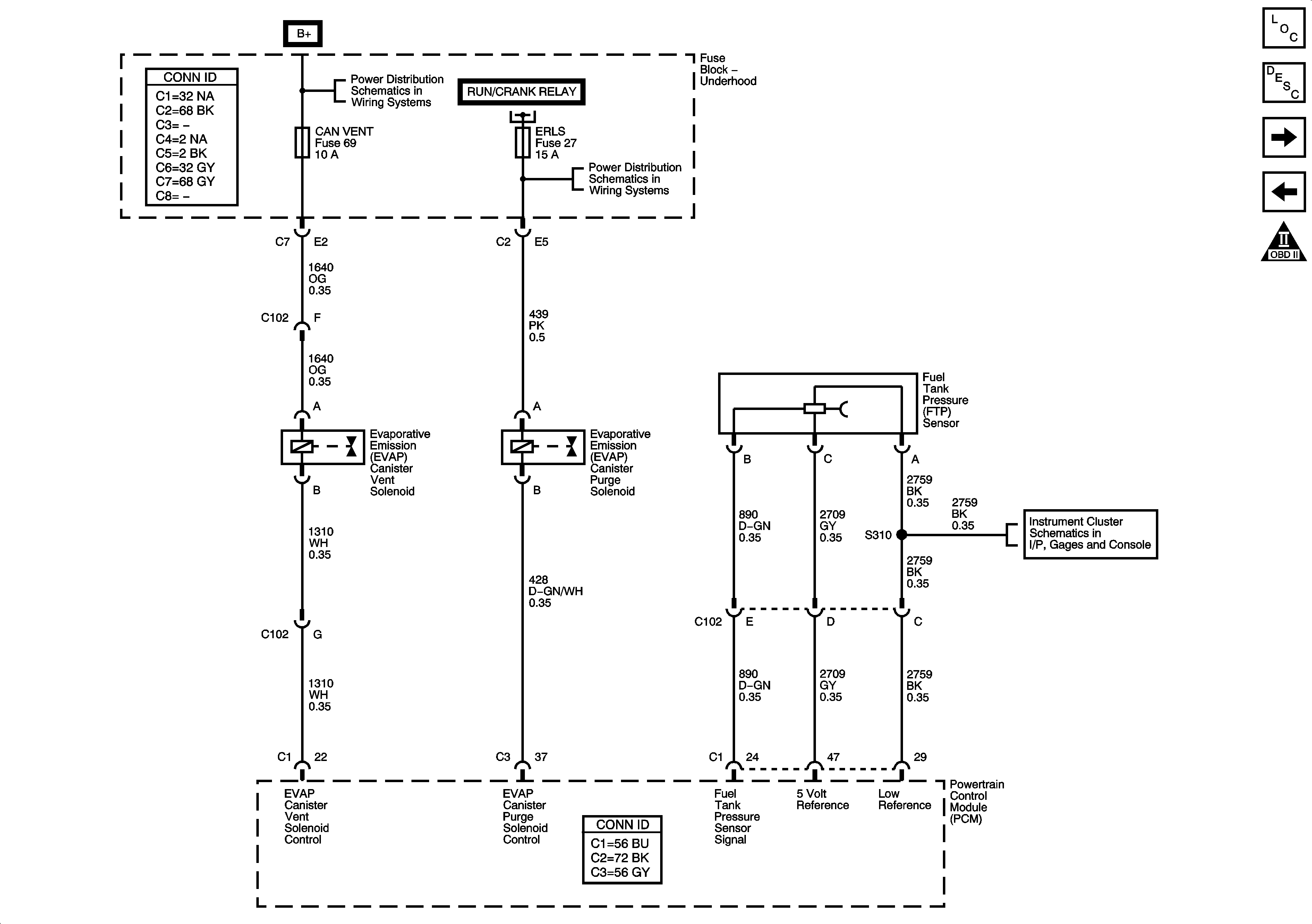
|
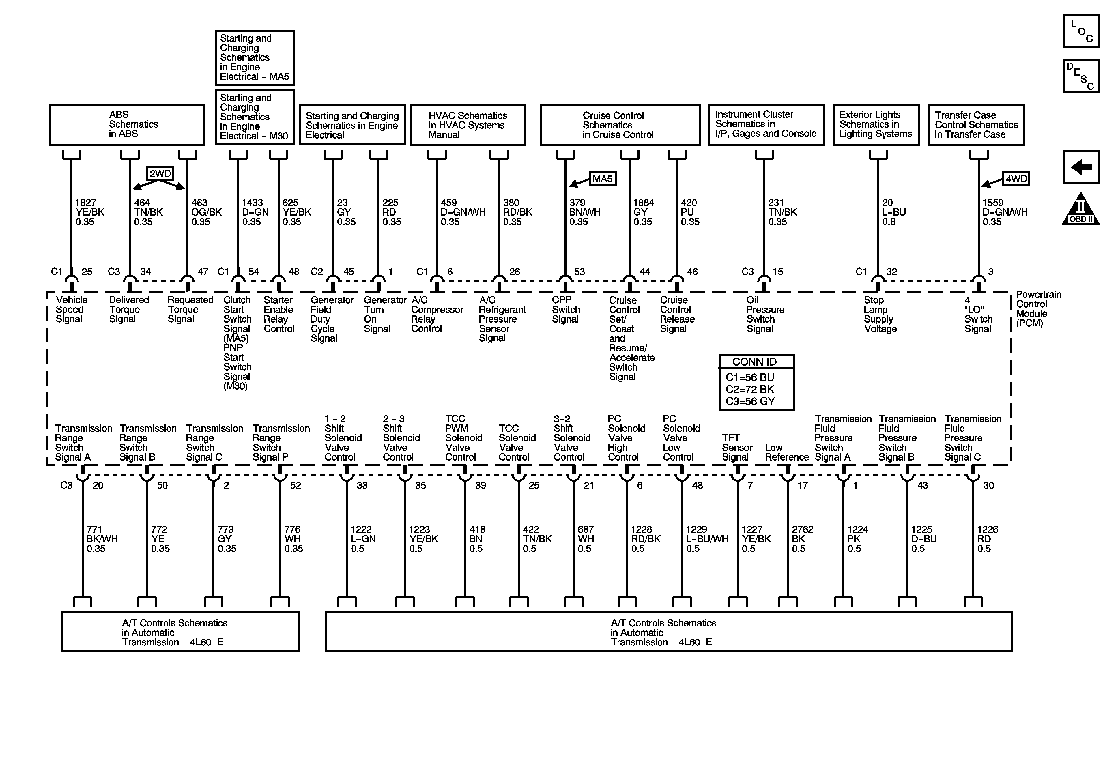
| Figure 10: |
Controlled/Monitored Subsystem and Transmission
References
|
