Tools Required
| • | J 37372 Bearing Installer |
| • | J 44749 Split Plate |
Removal Procedure
- Remove the propeller shaft. Refer to Two-Piece Propeller Shaft Replacement .
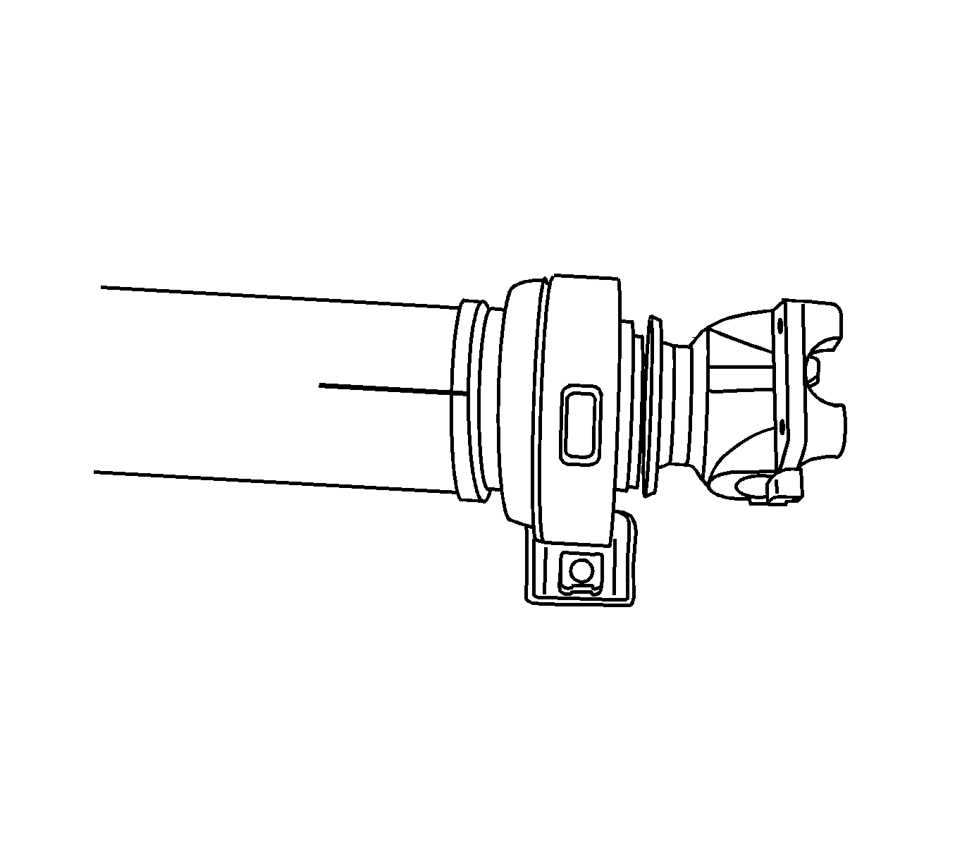
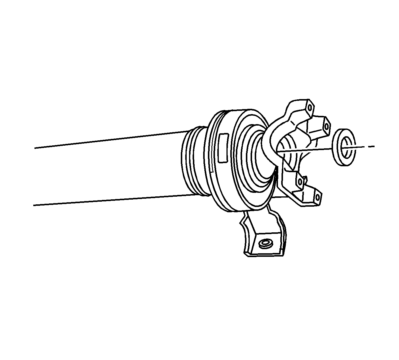
- Mark the relationship of the yoke to the driveshaft.
- Mark the relationship of the U-Joint to the yoke.
- Remove the U-Joint from the yoke.
- Using 2 or 3 clean shop towels, wrap the slip yoke with the towels and secure with electrical ties or electrical tape.
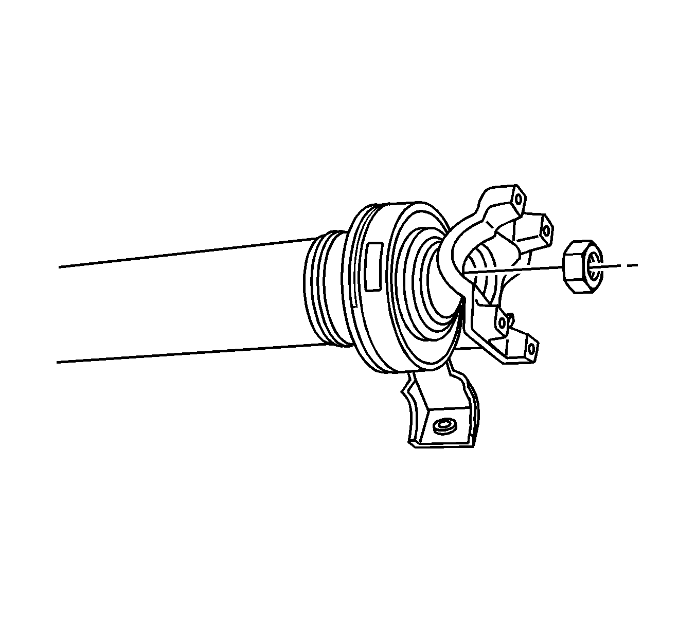
- Remove the retaining nut for the yoke.
- Remove the washer from the yoke.
- Remove the yoke from the propeller shaft.
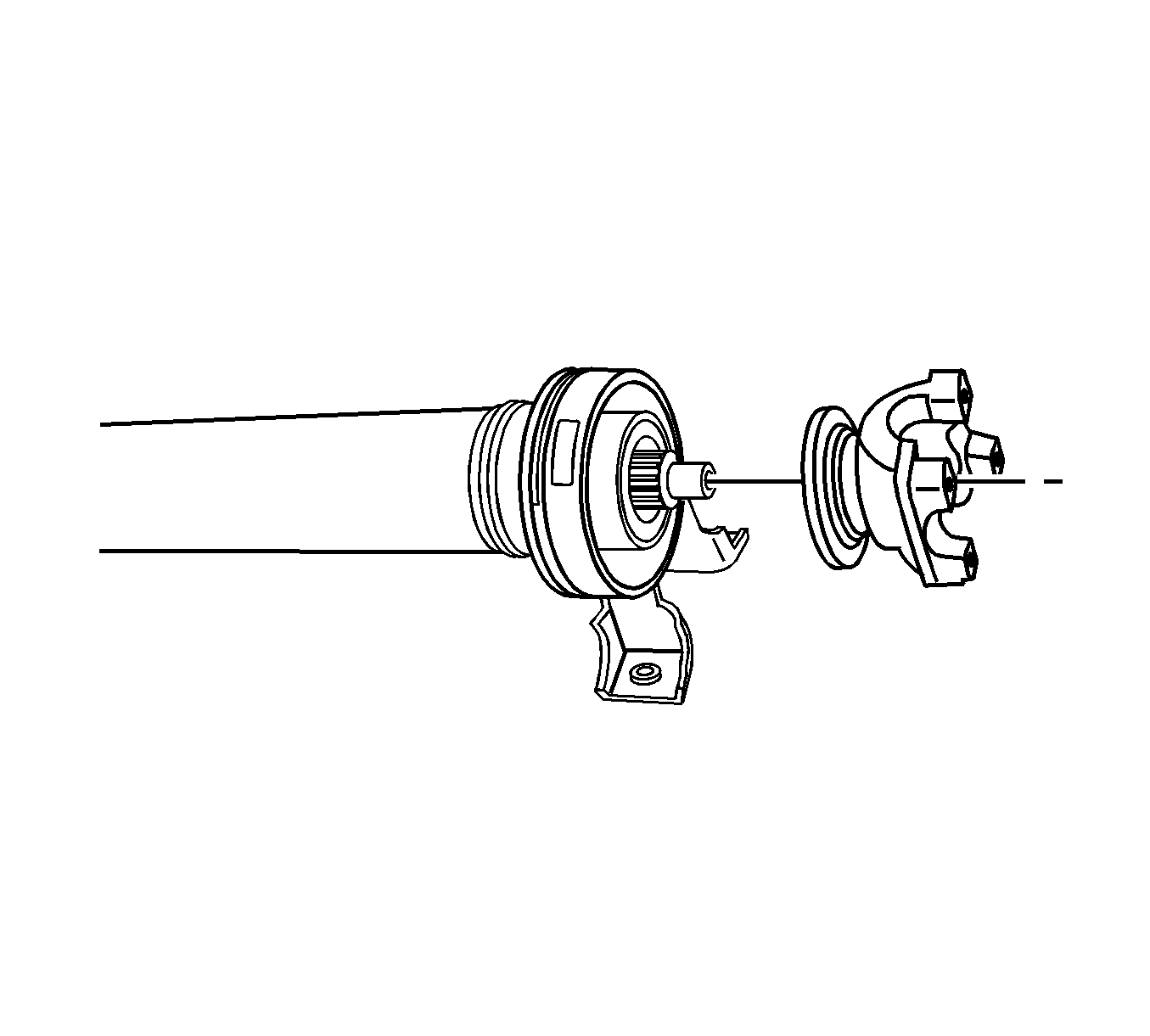
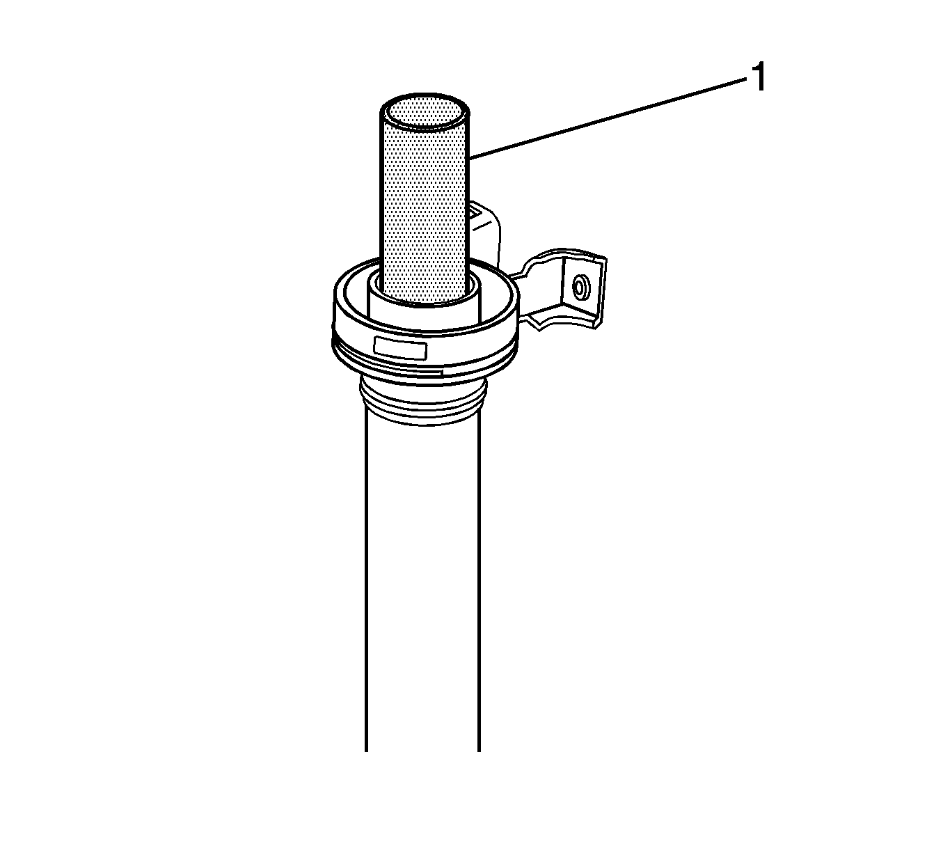
- Install the J 44749 (1) to the propeller shaft.
- Install the propeller shaft in a hydraulic press.
- Position a piece of wood between the floor and the slip yoke.
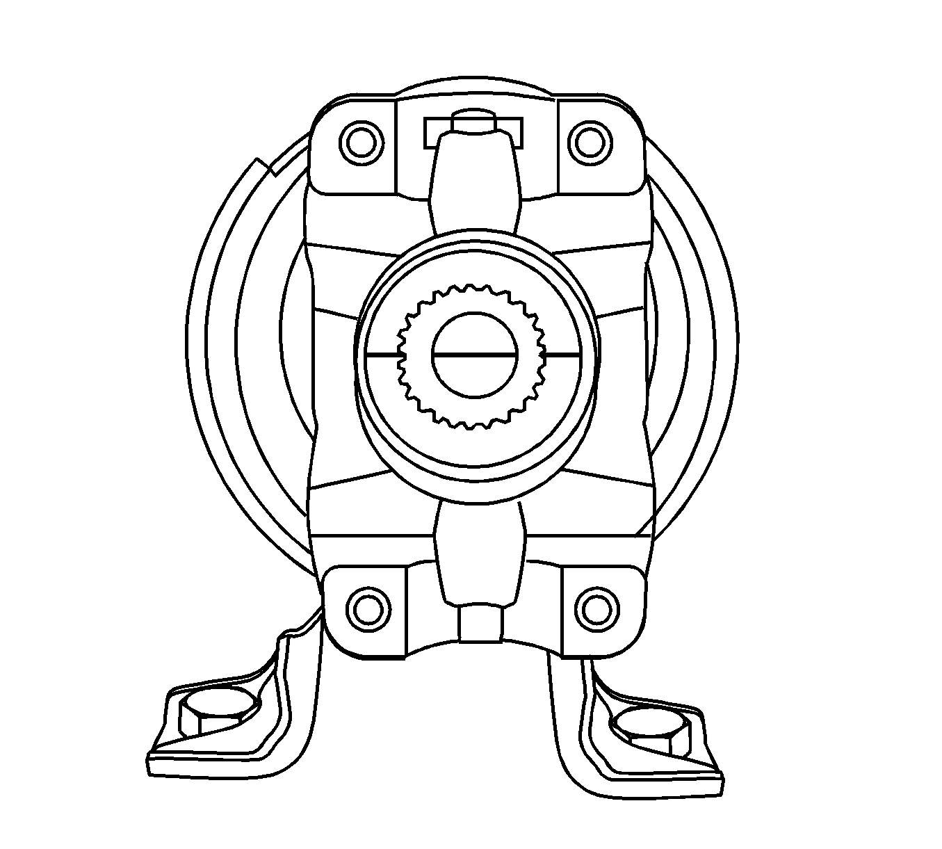
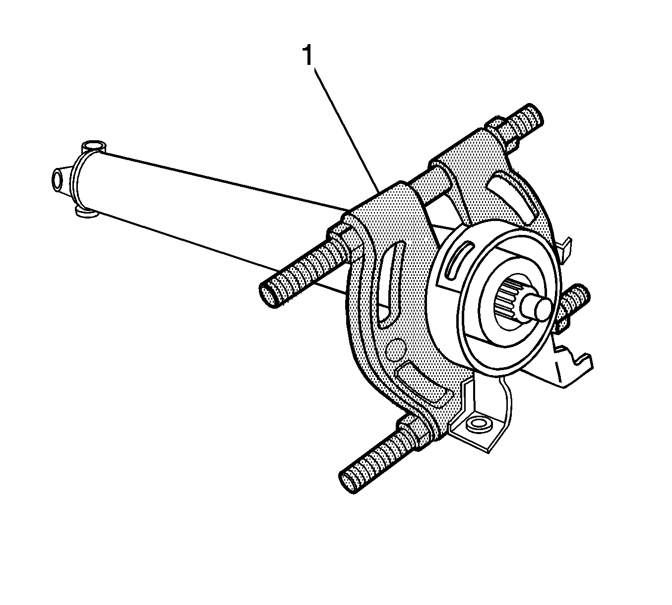
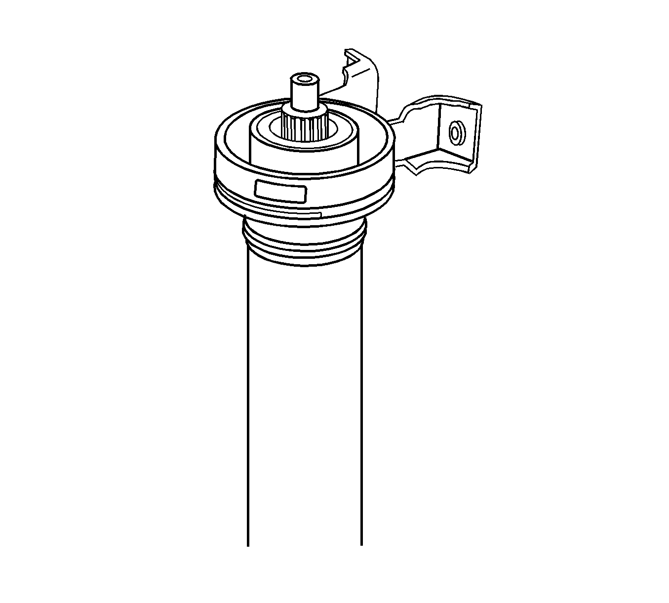
- Remove the center bearing (1) from the propeller shaft.
- Remove the tool from the propeller shaft.
Important: The following service is to protect the machined portion of the slip yoke.
Important: When installing the special tool, the aid of an assistant will be required to position the tool between the center bearing and propeller shaft shoulder. Ensure that the flat part of the tool is facing center bearing.
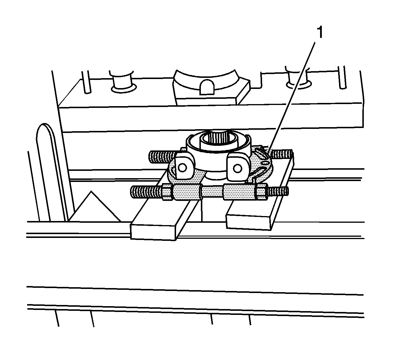
| 9.1. | With the aid of an assistant, pull the center bearing toward the spline part of the propeller shaft. |
| 9.2. | Position the tool (1) between the center bearing and the shield for the center bearing. |
| 9.3. | Adjust the tool so that it just comes in contact with the shoulder. |
Important: It will be necessary to adjust the hydraulic press so that the slip yoke does not touch the ground.
Installation Procedure
- Position the center bearing on the propeller shaft.
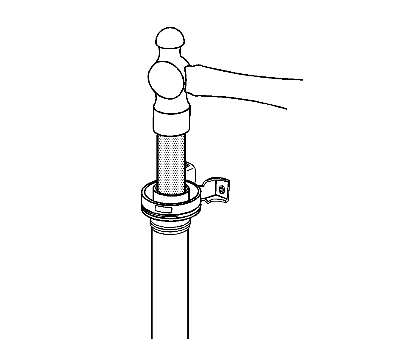
- Install the J 37372 on the propeller shaft.
- Using the J 37372 (1), install the center bearing on the propeller shaft.
- Position the yoke on the propeller shaft so that the reference marks are aligned properly.
- Using a brass or hard rubber hammer, lightly tap the yoke on the propeller shaft.
- Install the washer.
- Install the retaining nut.
- Align the U-Joint to the reference marks on the propeller shaft and yoke.
- Install the U-Joint to the yoke.
- Remove the shop towels from the propeller shaft.
- Install the propeller shaft in the vehicle. Refer to Two-Piece Propeller Shaft Replacement .
Important: Failure to align the reference marks properly will cause a vibration the propeller shaft.
Notice: Refer to Fastener Notice in the Preface section.
Important: Tighten the retaining nut by hand before tightening the retaining nut to the proper specifications.
Tighten
Tighten the retaining nut to 167 N·m (123 lb ft).
