Front Wheel Speed Sensor Replacement 2WD
Removal Procedure
Caution: Refer to Brake Dust Caution in the Preface section.
Caution: Refer to ABS Component Handling Caution in the Preface section.
- Raise and support the vehicle. Refer to Lifting and Jacking the Vehicle .
- Remove the wheel and tire. Refer to Tire and Wheel Removal and Installation .
- Remove the brake caliper bracket bolts (1).
- Without disconnecting the brake hose, remove the brake caliper and bracket (2) as an assembly and support with heavy mechanics wire or equivalent.
- Release the retainers securing the wheel speed sensor wiring harness to the upper control arm.
- Disconnect the wheel speed sensor electrical connector.
- Remove the speed sensor electrical connector from the body.
- Remove the wheel speed sensor harness bracket bolt (1).
- Using white or bright colored paint, mark the location of the speed sensor wiring harness to the steering knuckle.
- Remove the wheel hub/bearing bolts (2).
- Remove the brake rotor and the wheel hub/bearing as an assembly while routing the wheel speed sensor harness through the steering knuckle.
- Using white or bright colored paint, mark the location of the wheel speed sensor harness to the wheel hub/bearing assembly.
- Using a suitable tool, pry or lever the wheel speed sensor off of the wheel hub/bearing housing.
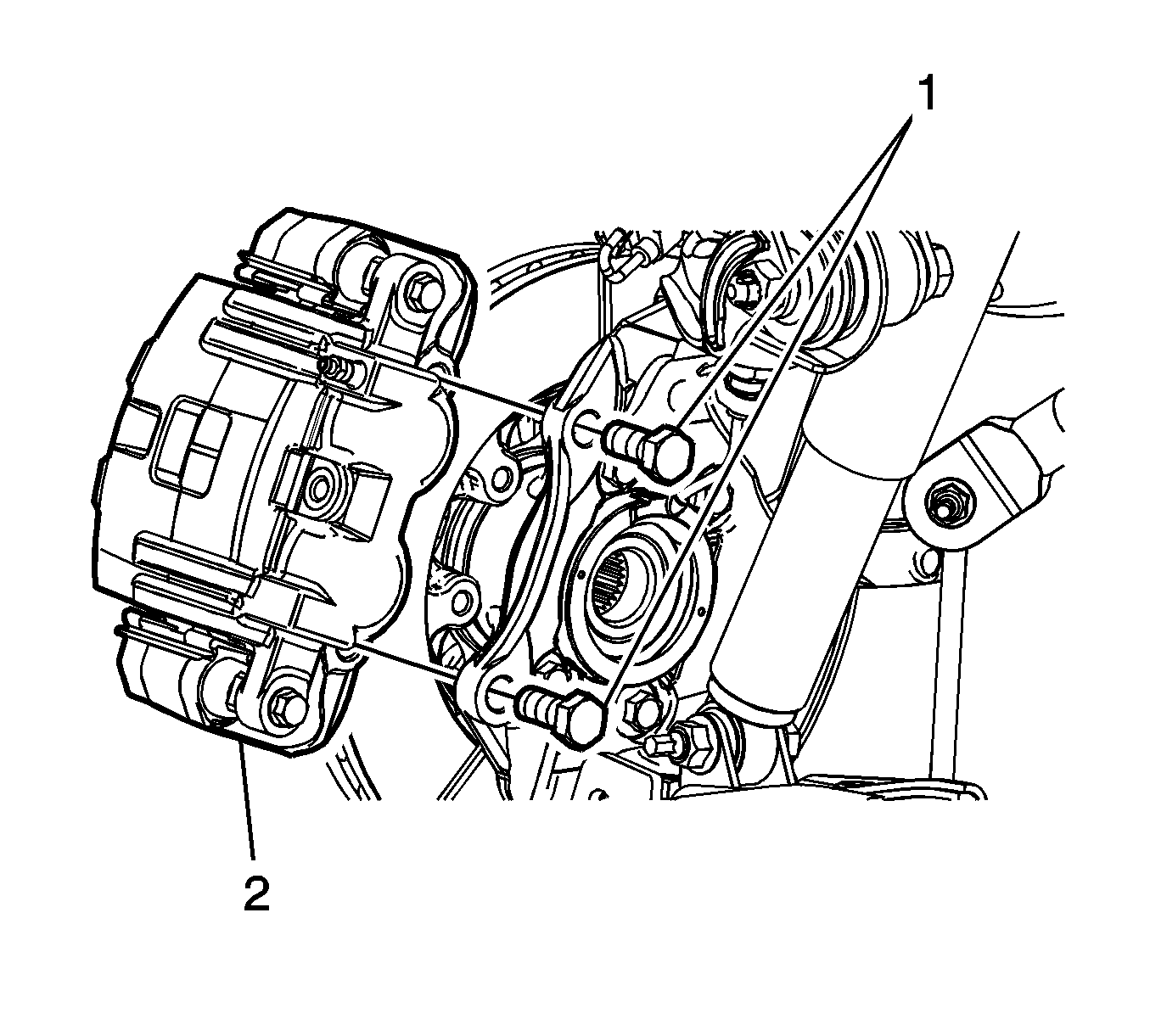
Notice: Support the brake caliper with heavy mechanic wire, or equivalent, whenever it is separated from its mount and the hydraulic flexible brake hose is still connected. Failure to support the caliper in this manner will cause the flexible brake hose to bear the weight of the caliper, which may cause damage to the brake hose and in turn may cause a brake fluid leak.
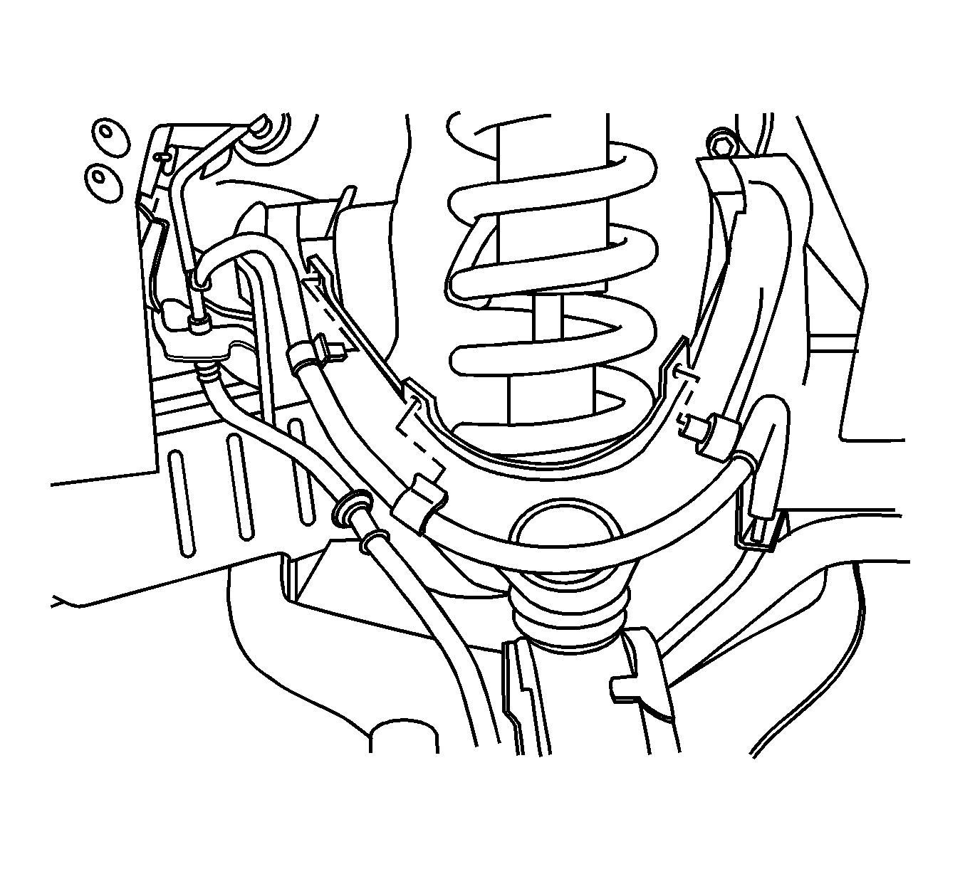
Important: Note the location of the retainers for the wheel speed sensor to the upper control arm and the body to assist installation and ensure correct harness routing.
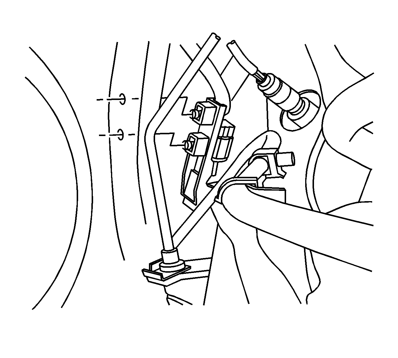
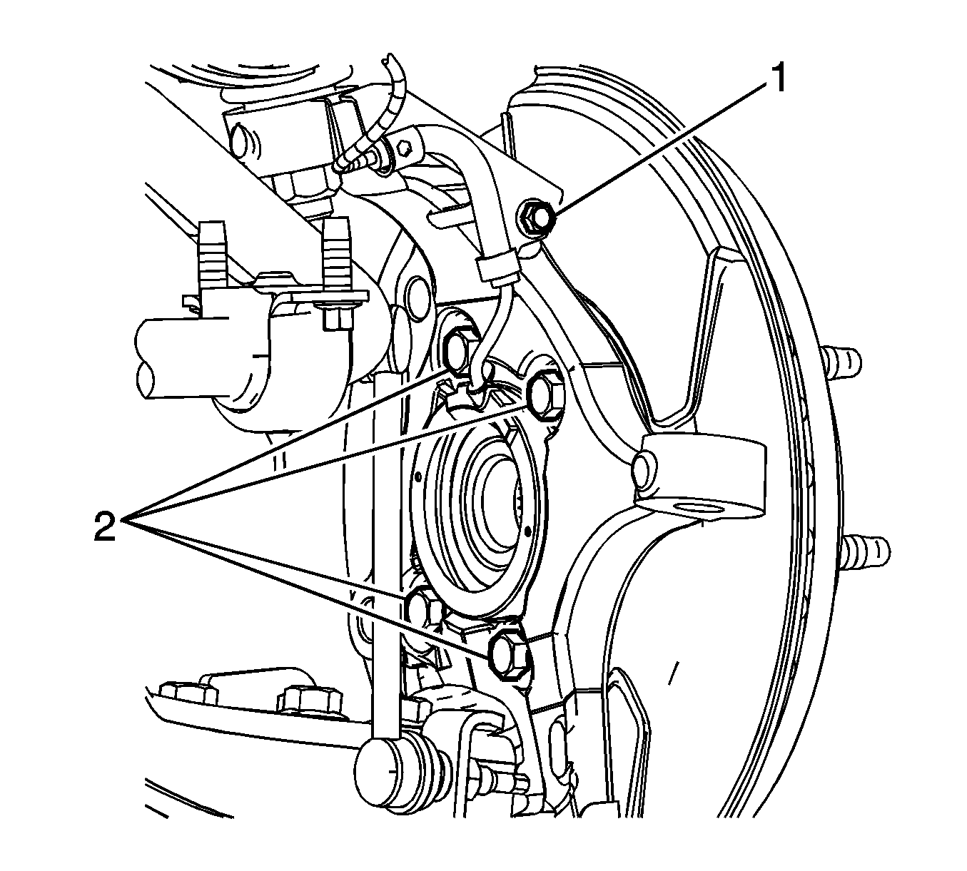
Important: Note that the wheel speed sensor harness is positioned between the wheel hub/bearing bolts at the narrowest span facing upward.
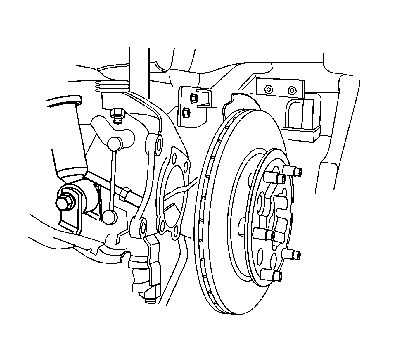
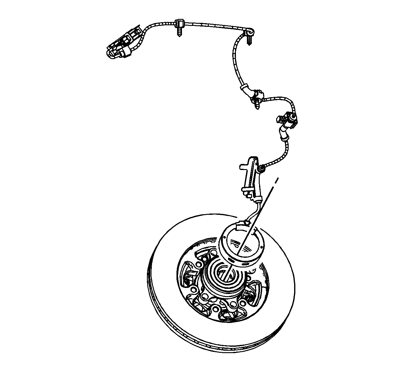
Important: Note that the wheel speed sensor harness is positioned at the narrowest span between the wheel hub/bearing bolt holes.
Important: DO NOT lever or pry against the wheel speed sensor tone wheel under the wheel speed sensor. Lever against the wheel hub ONLY.
Discard the wheel speed sensor.
Installation Procedure
- Position the wheel speed sensor on the wheel hub/bearing assembly.
- Carefully press the wheel speed sensor squarely onto the wheel hub/bearing assembly until fully seated against the lip of the wheel hub/bearing assembly housing.
- Install the wheel hub/bearing and brake rotor assembly to the steering knuckle with the wheel speed sensor harness positioned upward.
- Install the wheel hub/bearing bolts (2).
- Install the wheel speed sensor harness bracket bolt (1).
- Install the wheel speed sensor harness retaining clips to the upper control arm.
- Install the wheel speed sensor harness connector to the body.
- Connect the wheel speed sensor harness electrical connector.
- Install the brake caliper and bracket assembly (2) to the steering knuckle.
- Install the brake caliper bracket bolts (1).
- Install the tire and wheel. Refer to Tire and Wheel Removal and Installation .
- Lower the vehicle.
Important: Align the wheel speed sensor harness with the reference mark on the wheel hub/bearing assembly between the bolt holes narrowest span.

Important: Align the wheel speed sensor harness with the reference mark on the steering knuckle.

Notice: Refer to Fastener Notice in the Preface section.

Ensure the wheel speed sensor harness is positioned upward.
Tighten
Tighten the bolts to 125 N·m (92 lb ft).
Tighten
Tighten the bolt to 20 N·m (14 lb ft).


Tighten
Tighten the bolts to 175 N·m (129 lb ft).
Front Wheel Speed Sensor Replacement 4WD
Removal Procedure
Caution: Refer to Brake Dust Caution in the Preface section.
Caution: Refer to ABS Component Handling Caution in the Preface section.
- Remove the steering knuckle. Refer to Steering Knuckle Replacement.
- Remove the wheel speed sensor harness bracket bolt from the steering knuckle.
- Using white or bright colored paint, mark the location of the wheel speed sensor harness to the steering knuckle.
- Remove the wheel hub/bearing bolts (1).
- Remove the brake rotor (2) and the wheel hub/bearing as an assembly from the steering knuckle (3) while routing the wheel speed sensor harness through the steering knuckle.
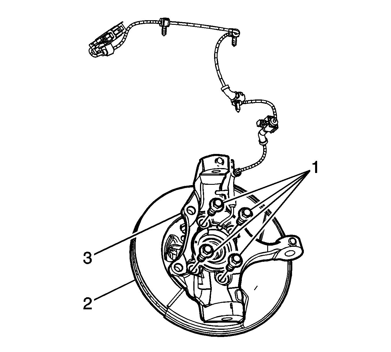
- Using white or bright colored paint, mark the location of the wheel speed sensor harness to the wheel hub/bearing assembly.
- Using a suitable tool, pry or lever the wheel speed sensor off of the wheel hub/bearing housing.
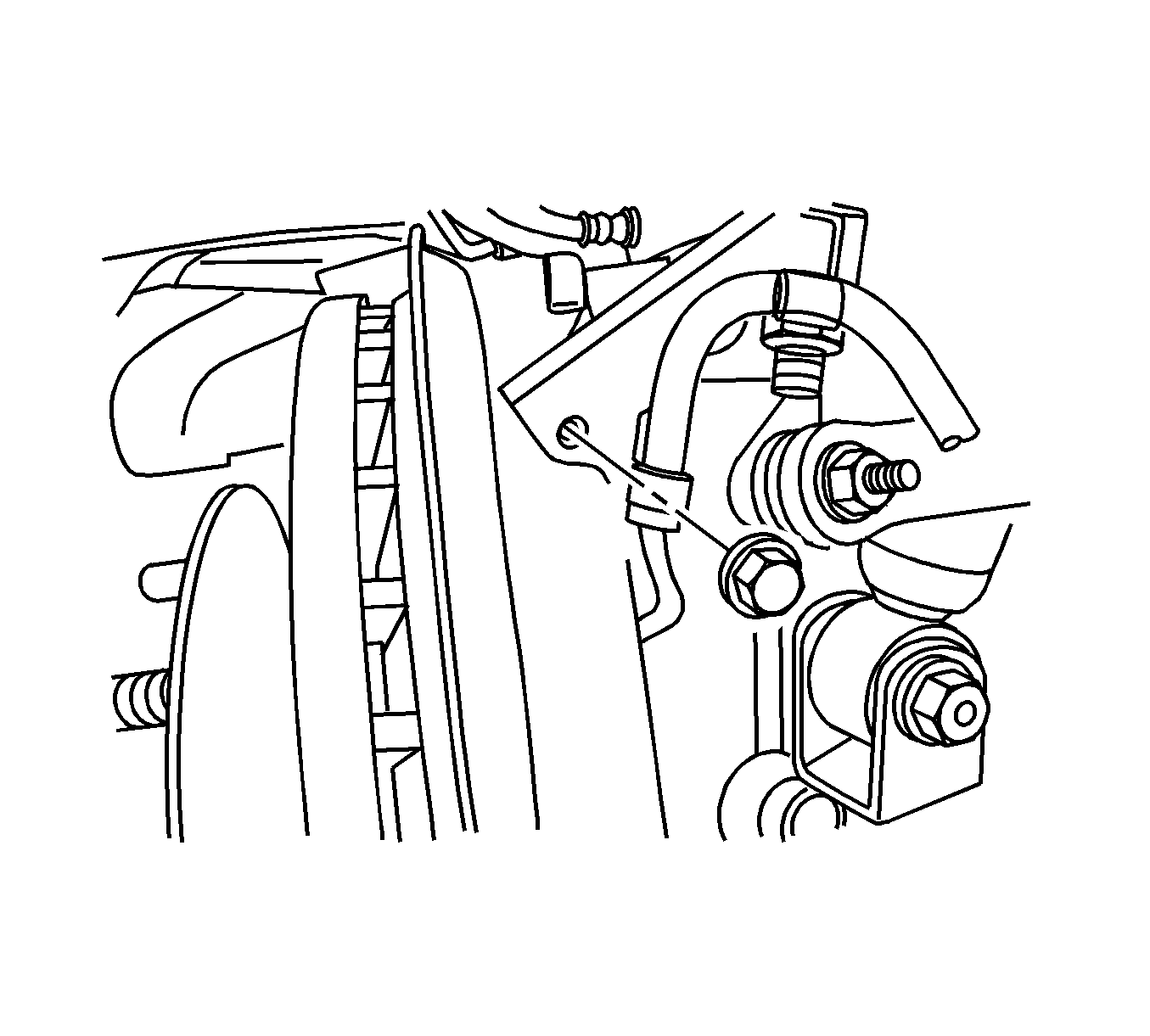
Important: Note that the wheel speed sensor harness is positioned between the wheel hub/bearing bolts at the narrowest span facing upward.

Important: Note that the wheel speed sensor harness is positioned at the narrowest span between the wheel hub/bearing bolt holes.
Important: DO NOT lever or pry against the wheel speed sensor tone wheel under the wheel speed sensor. Lever against the wheel hub ONLY.
Discard the wheel speed sensor.
Installation Procedure
- Position the wheel speed sensor on the wheel hub/bearing assembly.
- Carefully press the wheel speed sensor squarely onto the wheel hub/bearing assembly until fully seated against the lip of the wheel hub/bearing assembly housing.
- Install the wheel hub/bearing and brake rotor assembly (2) to the steering knuckle (3) with the wheel speed sensor harness positioned upward.
- Install the wheel hub/bearing bolts (1).
- Install the wheel speed sensor harness bracket bolt.
- Install the steering knuckle assembly. Refer to Steering Knuckle Replacement.
Important: Align the wheel speed sensor harness with the reference mark on the wheel hub/bearing assembly between the bolt holes narrowest span.

Notice: Refer to Fastener Notice in the Preface section.

Important: Align the wheel speed sensor harness with the reference mark on the steering knuckle.
Ensure the wheel speed sensor harness is positioned upward.
Tighten
Tighten the bolts to 125 N·m (92 lb ft).

Tighten
Tighten the bolt to 20 N·m (14 lb ft).
