For 1990-2009 cars only
Removal Procedure
- Remove the left side instrument panel (I/P) insulator panel. Refer to Instrument Panel Insulator Panel Replacement - Left Side .
- Remove the driver knee bolster. Refer to Driver Knee Bolster Replacement .
- Remove the accelerator pedal position sensor. Refer to Accelerator Pedal Position Sensor Replacement .
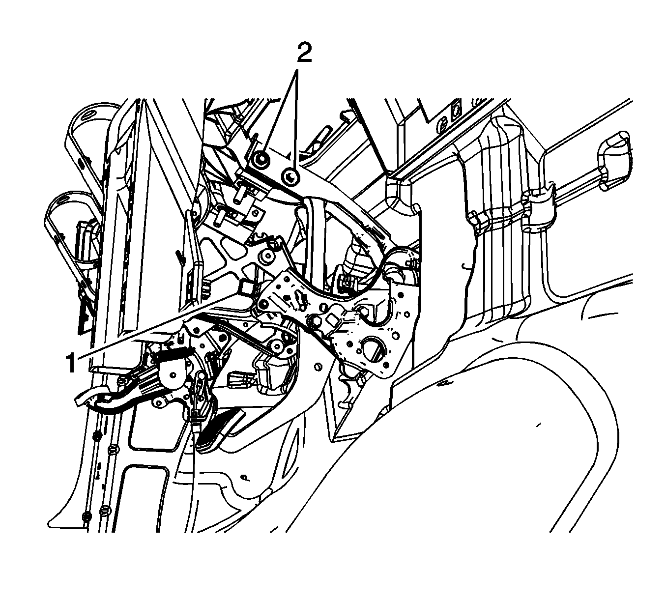
- Disconnect the brake pedal position sensor electrical connector (1).
- Remove the 2 brake pedal bracket bolts (2).
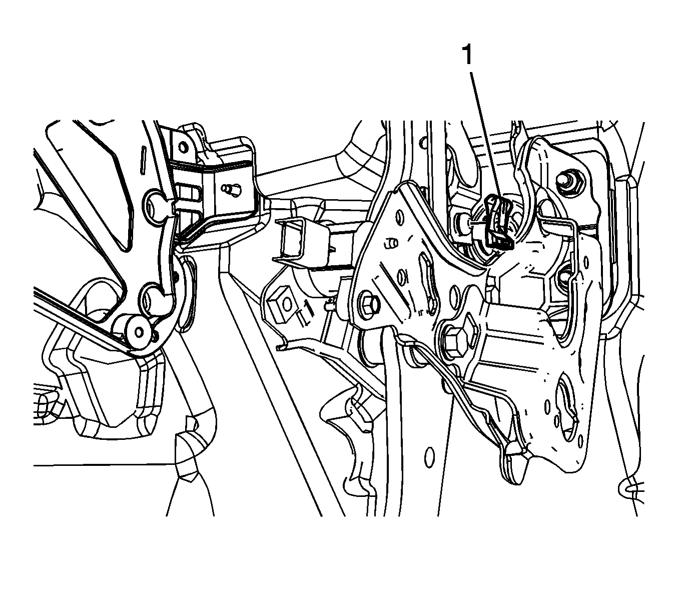
- Remove the brake pedal pushrod retainer (1).
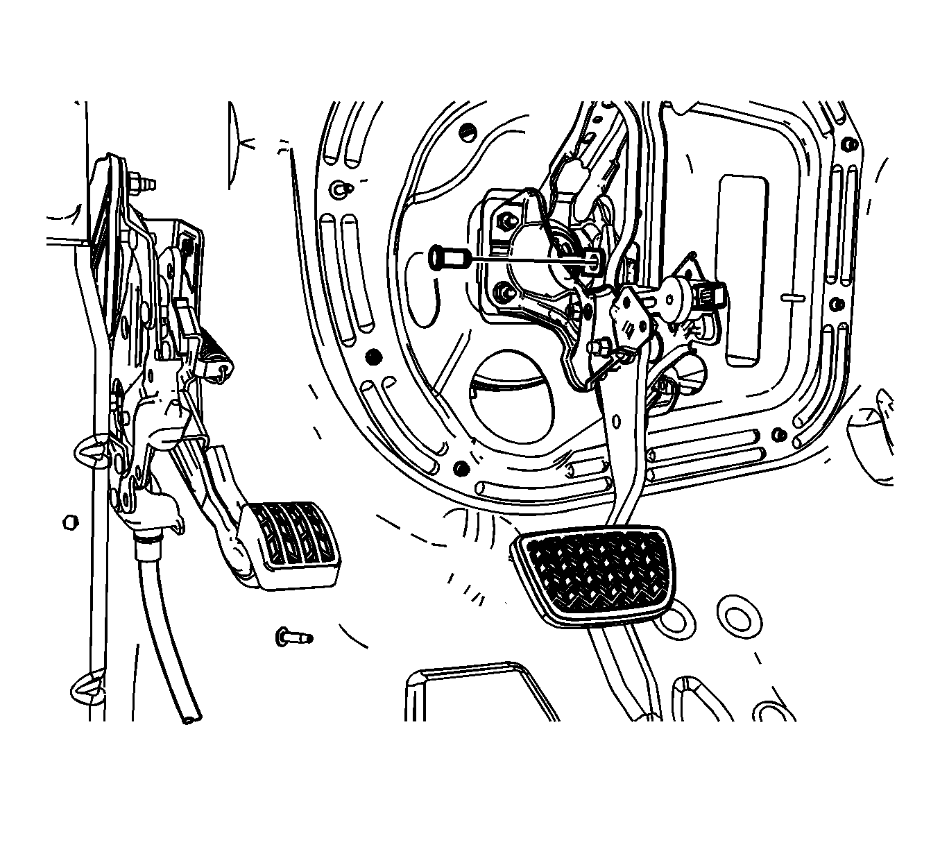
- Remove the brake pedal pushrod clevis pin.
- Remove the intermediate steering shaft. Refer to Intermediate Steering Shaft Replacement .
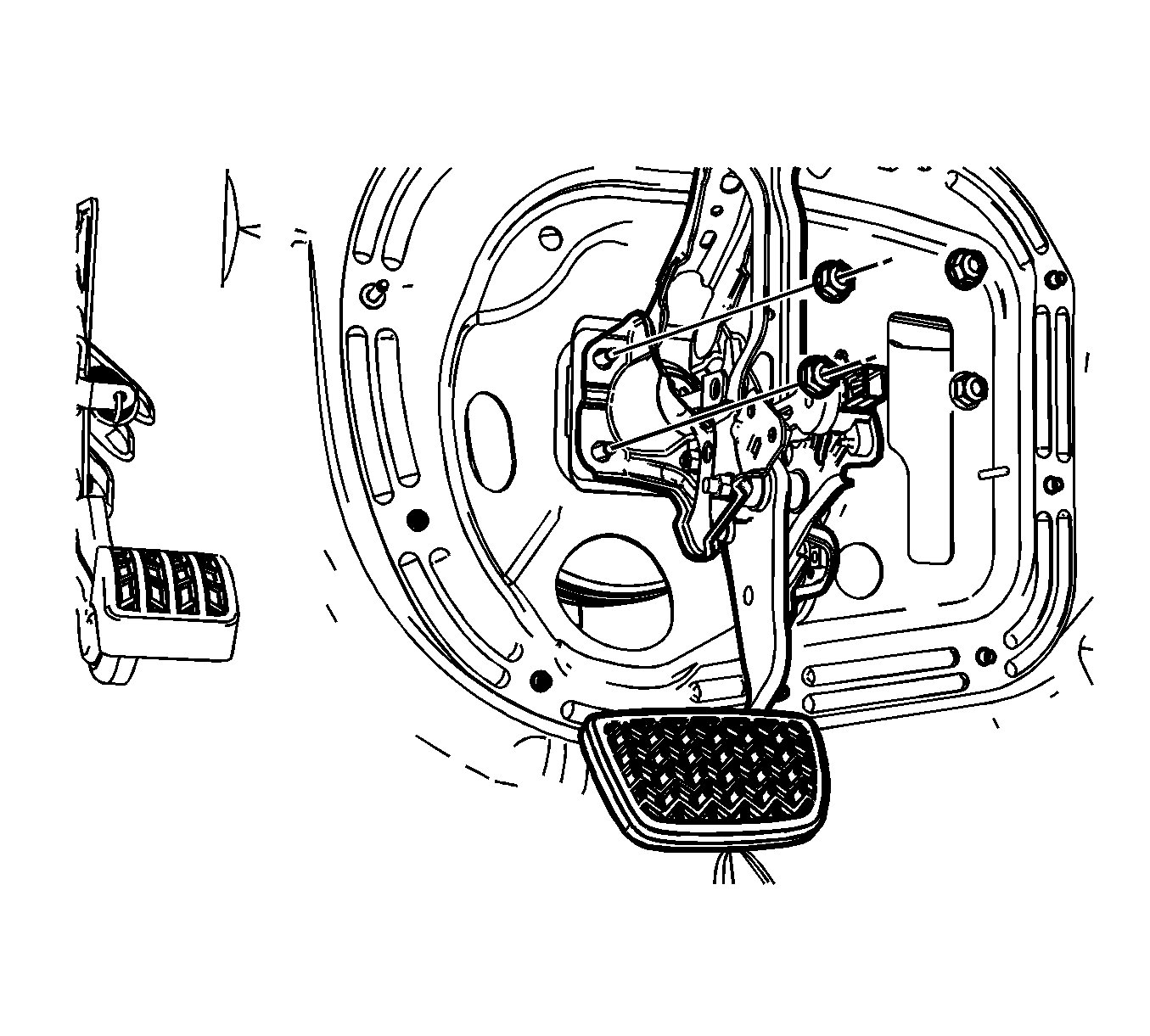
- Remove the 4 vacuum booster nuts.
- Position the vacuum brake booster and master cylinder assembly forward slightly to allow the brake pedal and bracket assembly to clear the booster studs.
- Remove the brake pedal assembly.


Installation Procedure
- Position the brake pedal assembly to the dash panel.
- Position the vacuum brake booster and master cylinder assembly to the dash panel.
- Install the 4 vacuum booster nuts.
- Position the brake pedal pushrod to the brake pedal.
- Install the brake pedal pushrod clevis pin.
- Install the brake pedal pushrod retainer (1).
- Install the intermediate steering shaft. Refer to Intermediate Steering Shaft Replacement .
- Install the 2 brake pedal bracket bolts (2).
- Connect the brake pedal position sensor electrical connector (1).
- Connect the brake pedal position sensor electrical connector.
- Install the accelerator pedal position sensor. Refer to Accelerator Pedal Position Sensor Replacement .
- Install the driver knee bolster. Refer to Driver Knee Bolster Replacement .
- Install the left side I/P insulator panel. Refer to Instrument Panel Insulator Panel Replacement - Left Side .
- Calibrate the brake pedal position sensor. Refer to Brake Pedal Position Sensor Calibration .

Notice: Refer to Fastener Notice in the Preface section.
Tighten
Tighten the nuts to 25 N·m (18 lb ft).


Tighten
Tighten the bolts to 22 N·m (16 lb ft).
