Special Tools
Cleaning Procedure
- Remove any old thread sealant, gasket material or sealant using
J 28410 .
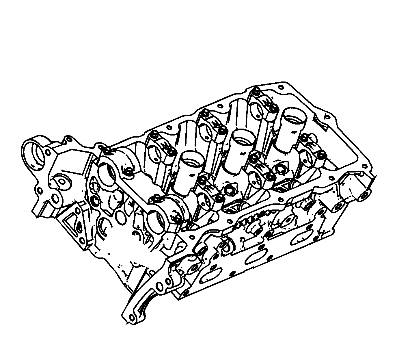
- Clean all cylinder head surfaces with non-corrosive solvent.
Caution: Refer to Safety Glasses Caution in the Preface section.
- Blow out all the oil galleries using compressed air.
- Remove any carbon deposits from the combustion chambers using the
J 8358 .
- Clean any debris or build-up from the lifter pockets.
Visual Inspection

- Inspect the cylinder head camshaft bearing surfaces for the following conditions:
| • | Excessive scoring or pitting |
| • | Discoloration from overheating |
| • | Deformation from excessive wear |
| • | If the camshaft bearing journals appear to be scored or damaged, you must replace the cylinder head. DO NOT machine the camshaft bearing journals. |
- If any of the above conditions exist on the camshaft bearing surfaces, replace the cylinder head.
- Inspect the cylinder head for the following:
| • | Cracks, damage or pitting in the combustion chambers |
| • | Debris in the oil galleries -- Continue to clean the galleries until all debris is removed. |
| • | Coolant leaks or damage to the deck face sealing surface -- If coolant leaks are present, measure the surface warpage as described under Cylinder Head Measurement - Deck Flatness Inspection. |
| • | Burrs or any defects that would degrade the sealing of the NEW secondary camshaft drive chain tensioner gasket |
| • | Damage to any gasket surfaces |
| • | Damage to any threaded bolt holes |
| • | Burnt or eroded areas in the combustion chamber |
| • | Cracks in the exhaust ports and combustion chambers |
| • | External cracks in the water passages |
| • | Restrictions in the intake or exhaust passages |
| • | Restrictions in the cooling system passages |
| • | Rusted, damaged or leaking core plugs |
- If the cylinder head is cracked or damaged, it must be replaced. No welding or patching of the cylinder head is recommended.

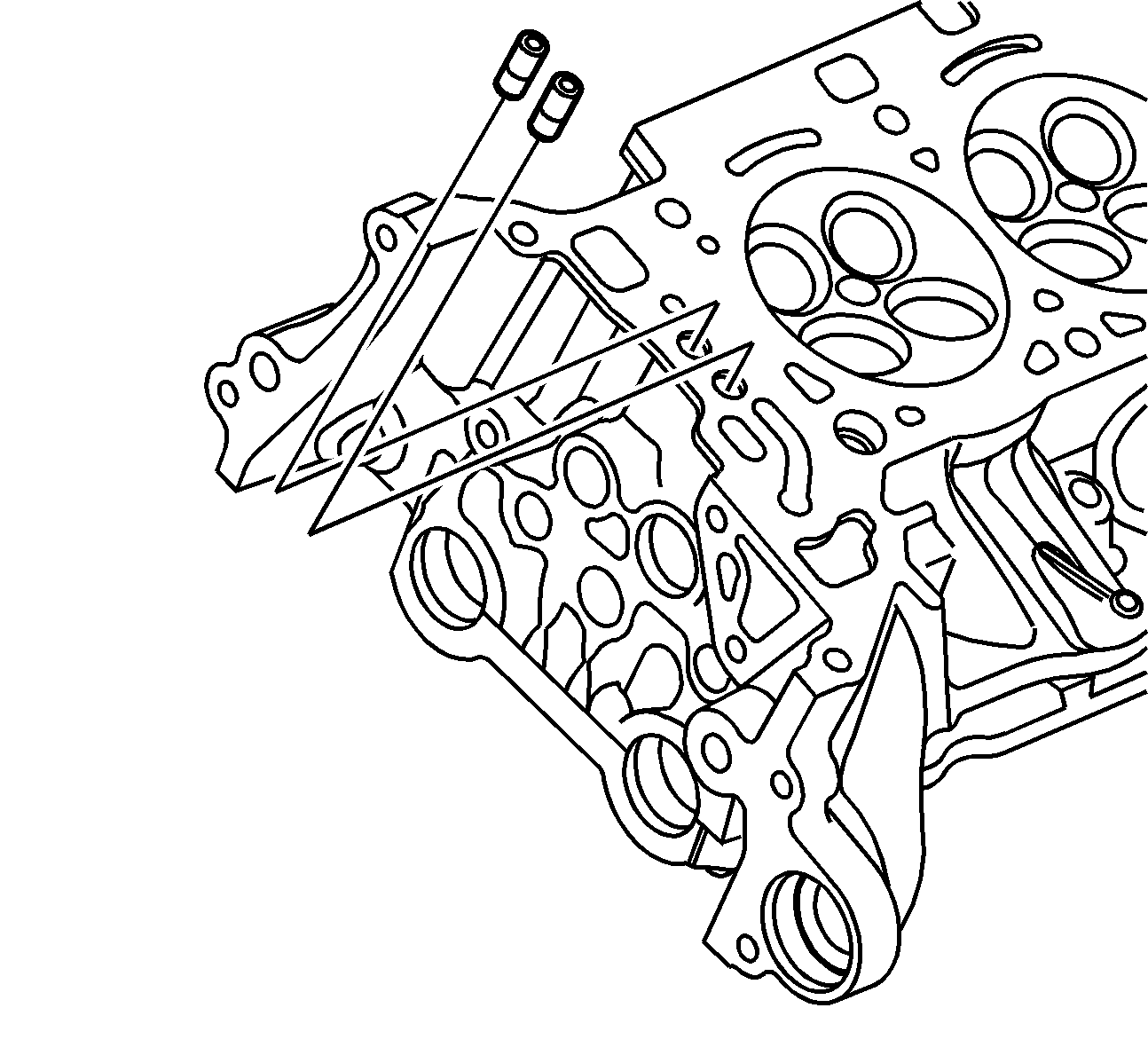
- Inspect the camshaft position actuator oil feed check valves. Damaged, restricted or clogged check valves must be replaced. Refer to
Cylinder Head Disassemble.
Cylinder Head Measurement
Camshaft Journal Clearance
- Install the camshaft bearing cap in the cylinder head without the camshaft.
Notice: Refer to Fastener Notice in the Preface section.
- Install the camshaft cap bolts.
Tighten
Tighten the camshaft cap bolts to 10 N·m (89 lb in).
- Measure the camshaft bearings using an inside micrometer.
- Subtract the camshaft journal diameter from the camshaft bearing diameter. This will provide the running clearance. If the running clearance exceeds specifications and the camshaft journals are within specification, replace the cylinder head. Refer
to
Engine Mechanical Specifications.
Camshaft Journal Alignment
- Ensure the camshafts are serviceable.
- Inspect the cylinder head camshaft bearing surfaces for any imperfections or scratches that could inhibit proper camshaft clearances. Repair minor imperfections or scratches.
- Install the camshafts in the cylinder head.
- Install the camshaft bearing caps.
- Install the camshaft cap bolts.
Tighten
Tighten the camshaft cap bolts to 10 N·m (89 lb in).
- Ensure the camshafts spin freely in the cylinder head. If the camshaft does not run freely, replace the cylinder head.
Deck Flatness Inspection

- Ensure the cylinder head decks are clean and free of gasket material.
- Inspect the surface for any imperfections or scratches that could inhibit proper cylinder head gasket sealing.
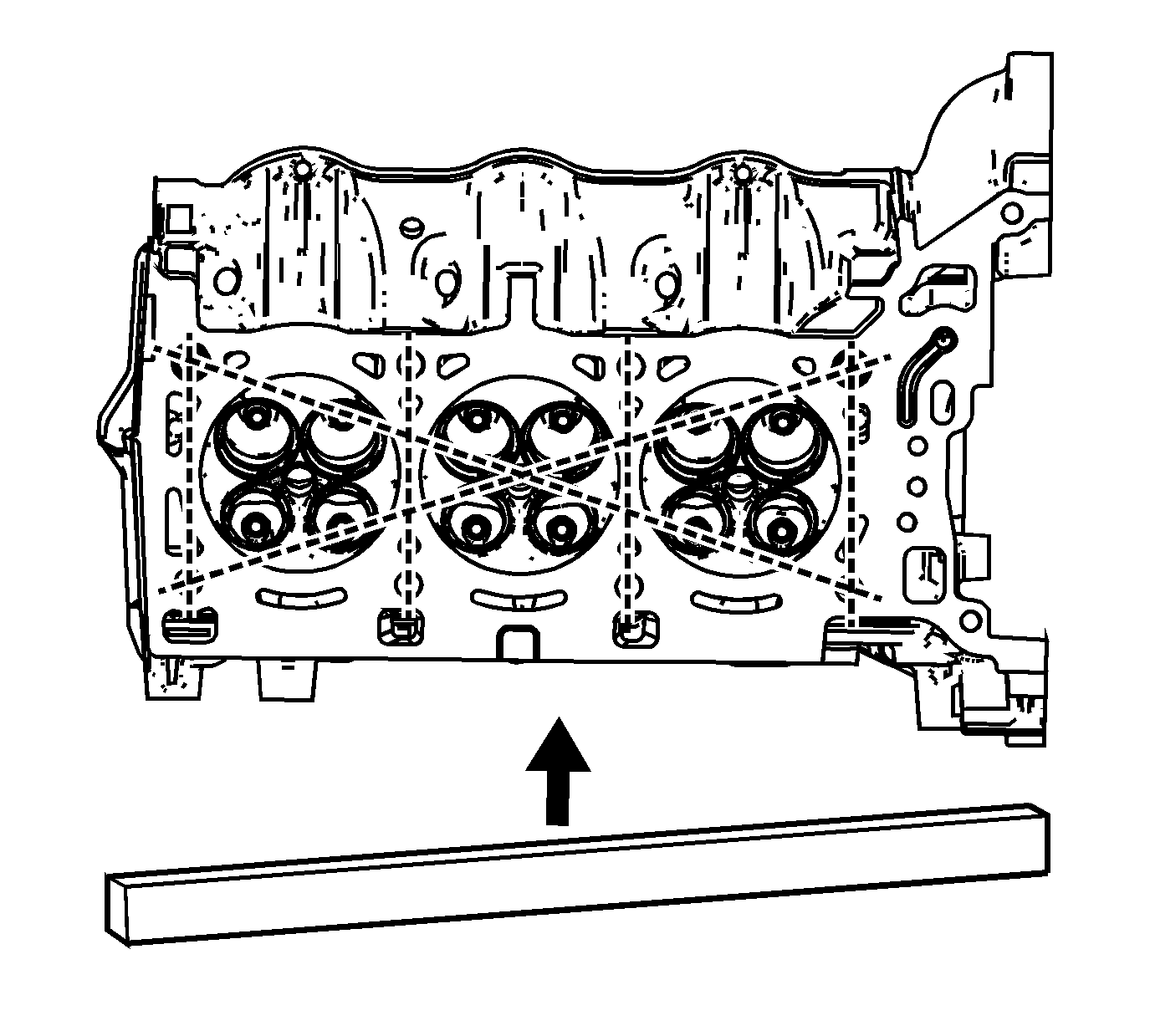
- Place a straight-edge diagonally across the cylinder head deck face surface.
- Measure the clearance between the straight-edge and the cylinder head deck face using a feeler gage at 4 points along the straight-edge.
- If the warpage is less than 0.05 mm (0.002 in), the cylinder head deck surface does not require resurfacing.
- If the warpage is between 0.05-0.20 mm (0.002-0.008 in) or any imperfections or scratches that could inhibit proper cylinder head gasket sealing are present, the cylinder head deck surface requires resurfacing.
- If resurfacing is required the maximum amount that can be removed is 0.25 mm (0.010 in).
- If the cylinder head deck surface requires more than 0.25 mm (0.010 in) material removal the head must be replaced.
Valve Guide Measurement

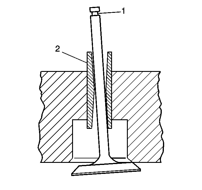
- Measure the valve stem (1)-to-guide (2) clearance. Excessive valve stem-to-guide clearance may cause an excessive oil consumption and may also cause a valve to break. Insufficient clearance
will result in noisy and sticky functioning of the valve and will disturb the engine assembly smoothness.
- Clamp the
J 8001 to the cylinder head at the camshaft cover rail.
- Locate the dial indicator so that the movement of the valve stem from side to side, crossways to the cylinder head, will cause a direct movement of the indicator stem. The dial indicator stem must contact the side of the valve stem just above the
valve guide.
- Drop the valve head about 0.064 mm (0.0025 in) off the valve seat.
- Use light pressure when moving the valve stem from side to side in order to obtain a clearance reading. Refer to
Engine Mechanical Specifications for proper clearance.
| • | If the clearance for the valve is greater than specifications and a new standard diameter valve stem will not bring the clearance within specifications, the valve guide may be oversized by 0.075 mm (0.003 in) using the
J 42096 . There is 1 size of oversized valve stem available for service. |
| • | Valve guide wear at the bottom 10 mm (0.390 in) of the valve guide is not significant to normal operation. |
| • | If oversizing the guide does not bring the clearance within specifications, replace the cylinder head. |


