For 1990-2009 cars only
Removal Procedure
- Raise and support the vehicle. Refer to Lifting and Jacking the Vehicle.
- Remove the tire and wheel. Refer to Tire and Wheel Removal and Installation.
- Remove wheel speed sensor wiring harness from control arm and steering knuckle.
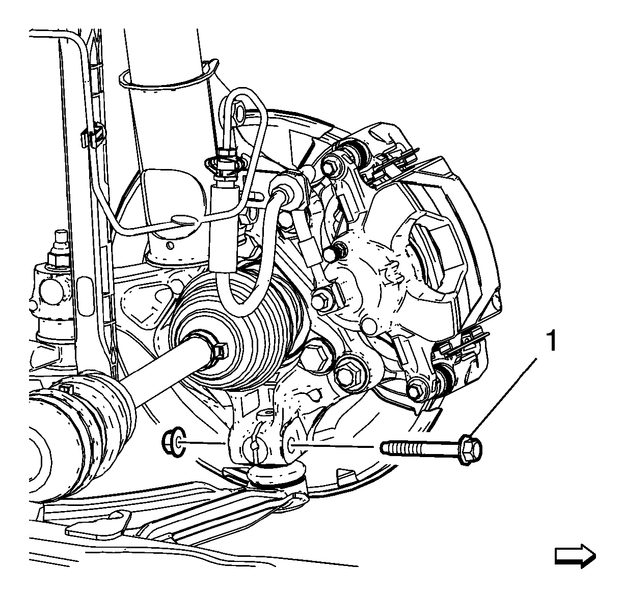
- Remove the lower ball joint to knuckle nut and bolt (1).
- Separate the lower control arm from the knuckle.
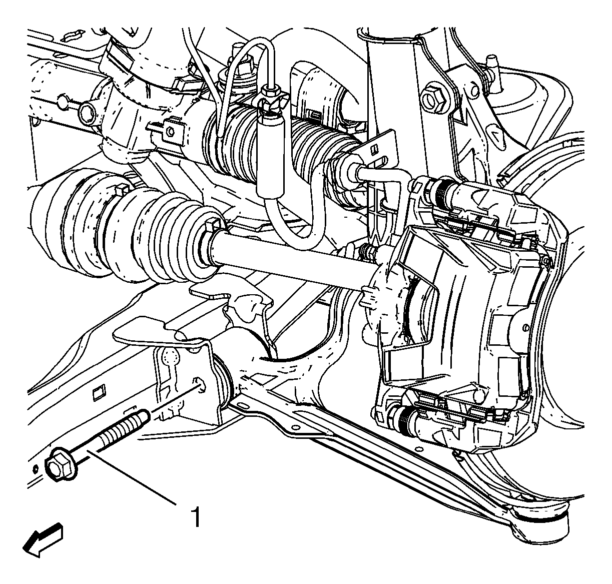
- Remove the front lower control arm nut and bolt (1).
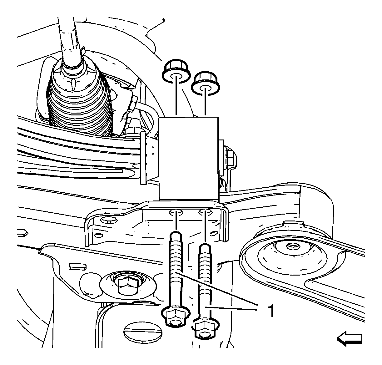
- Remove the rear lower control arm bushing nuts and bolts (1).
- Remove the lower control (1) arm from the front frame.
Note: DO NOT re-use the lower ball joint bolt. Discard and use NEW only.

Installation Procedure
- Position the lower control arm (1) in the cradle.
- Install and hand tighten the rear lower control arm bushing nuts and bolts (1).
- Install and hand tighten the front lower control arm nut and bolt.
- Install the ball joint to knuckle bolt and nut and tighten to XX N·m (xx lb ft).
- Load the front suspension with the proper jack stand before tightening the bolts to specifications.
- Tighten the front lower control arm bolt to XX N·m (xx lb ft).
- Tighten the rear bushing to frame bolts to XX N·m (xx lb ft).
- Remove the jack stand.
- Install the tire and wheel. Refer to Tire and Wheel Removal and Installation.
- Lower the vehicle.
Caution: Refer to Fastener Caution in the Preface section.
