SIR System Overview
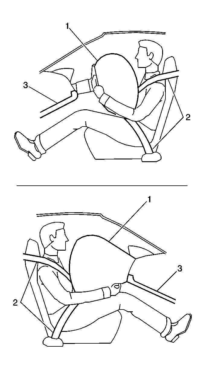
The supplemental inflatable restraint (SIR) system supplements the protection offered by the occupant's seat belt system (2). The SIR system may contain several inflator modules located throughout the vehicle, i.e. steering wheel module (1), instrument panel (I/P) module (1), side impact modules, and front seat belt pretensioners. Each inflator module and seat belt pretensioner has a deployment loop that is controlled by the sensing and diagnostic module (SDM) mounted inside the vehicle. The SDM determines the severity of a collision with the assistance of various sensor inputs. When the SDM detects a collision of sufficient force it will process the information provided by the sensors to further support air bag deployment. The SDM performs continuous diagnostic monitoring of the SIR system electrical components. Upon detection of a circuit malfunction, the SDM will set a DTC and inform the driver by requesting the instrument panel cluster (IPC) to turn the AIR BAG indicator ON. The steering column (1) and knee bolsters (3) are designed to absorb energy and compress during frontal collisions in order to limit leg movement and decrease the chance of injury to the driver and passenger.
Frontal SIR System Description
The frontal SIR system consists of the following components:
| • | AIR BAG indicator located on the instrument panel cluster (IPC) |
| • | Driver and passenger knee bolsters |
| • | Inflatable restraint front end sensor (left/right) |
| • | Inflatable restraint (I/P) module |
| • | Inflatable restraint seat belt pretensioner (left/right) |
| • | Inflatable restraint sensing and diagnostic module (SDM) |
| • | Inflatable restraint steering wheel module |
| • | Inflatable restraint steering wheel module coil |
| • | Inflatable restraint wiring harnesses |
| • | Steering wheel and column |
A frontal collision of sufficient force will deploy the frontal air bags and seat belt pretensioners. The SDM contains a sensing device that converts vehicle velocity changes to an electrical signal. In the event of a frontal collision, the SDM receives a signal from the front end sensors which assists the SDM in determining the severity of some frontal collisions. The SDM contains a microprocessor that performs calculations using the measured accelerations. The SDM compares these calculations to a value stored in memory. When the generated calculations exceed the stored value, the SDM will cause current to flow through the frontal deployment loops deploying the frontal air bags and pretensioners. Once the air bags are inflated they quickly deflate through the air bag vent holes. After the air bags and pretensioners have deployed, the SDM sets a diagnostic trouble code (DTC) and requests the instrument panel cluster (IPC) to turn the AIR BAG indicator ON. The SDM, I/P module, steering wheel module, steering wheel module coil, seat belt pretensioners and the connecting wires makeup the frontal deployment loops. The SDM continuously monitors the deployment loops for malfunctions and requests the IPC to turn the AIR BAG indicator ON if a fault is detected.
Inflatable Restraint Sensing and Diagnostic Module (SDM)
The sensing and diagnostic module (SDM) is a microprocessor and the control center for the SIR system. The SDM contains internal sensors along with several external sensors, if equipped, mounted at various locations on the vehicle. In the event of a collision, the SDM performs calculations using the signals received from the internal and external sensors. The SDM compares the results of the calculations to values stored in memory. When these calculations exceed the stored value, the SDM will cause current to flow through the appropriate deployment loops to deploy the air bags and seat belt pretensioners. The SDM records the SIR system status when a deployment occurs and requests the instrument panel cluster (IPC) to turn the AIR BAG indicator ON. The SDM performs continuous diagnostic monitoring of the SIR system electrical components and circuitry when the ignition is turned ON. If the SDM detects a malfunction, a DTC will be stored and the SDM will request the IPC to turn the AIR BAG indicator ON. In the event that ignition 1 voltage is lost during a collision, the SDM maintains a 23-volt loop reserve (23 VLR) for deployment of the air bags. It is important to note, when disabling the SIR system for servicing or rescue operations to allow the 23 VLR to dissipate, which could take up to 1 minute.
AIR BAG Indicator
The AIR BAG indicator, located on the instrument panel cluster (IPC) is used to notify the driver of SIR system malfunctions and to verify that the SDM is communicating with the IPC. When the ignition is turned ON, the SDM is supplied with ignition 1 voltage and requests the IPC to flash the AIR BAG indicator 7 times. While flashing the indicator, the SDM conducts test on all SIR system components and circuits. If no malfunctions are detected the SDM will communicate with the IPC through the class 2 serial data circuit and request the IPC to turn the AIR BAG indicator OFF. The SDM provides continuous monitoring of the air bag circuits by conducting a sequence of checks. If a malfunction is detected the SDM will store a diagnostic trouble code (DTC) and request the IPC to turn the AIR BAG indicator ON. The presence of a SIR system malfunction could result in non-deployment of the air bags. The AIR BAG indicator will remain ON until the malfunction has been repaired.
Dual Stage Inflator Modules
Dual stage inflator modules contain a housing, inflatable air bag, two initiating devices, canister of gas generating material and, in some cases, stored compressed gas. The two initiators are part of the inflator module deployment loop. The inflator modules have two stages of deployment, which varies the amount of restraint to the occupant according to the collision severity. For moderate frontal collisions the inflator modules deploy at less than full deployment which consists of stage 1 of the inflator module. For more severe frontal collisions a full deployment is initiated which consists of stage 1 and stage 2 of the inflator module. When the vehicle is involved in a collision of sufficient force, the SDM will cause current to flow through the deployment loops to the initiator. Current passing through the initiator ignites the material in the canister producing a rapid generation of gas and the release of compressed gas, if present. The gas produced from this reaction rapidly inflates the air bag. Once the air bag is inflated it quickly deflates through the air bag vent holes.
Each dual stage inflator module is equipped with a shorting bar located on the connector(s) of the module. The shorting bar shorts the inflator module deployment loop circuitry to prevent unwanted deployment of the air bag when it is disconnected.
Inflatable Restraint Steering Wheel Module Coil
The steering wheel module coil is attached to the steering column and is located under the steering wheel. The steering wheel module coil consists of two or more current-carrying coils. The coils allow the rotation of the steering wheel while maintaining continuous electrical contact between the driver deployment loop and the steering wheel module. Four coil wires are used for the steering wheel module deployment loop. Additional coil wires are used for accessories attached to the steering wheel depending on the vehicle model. The steering wheel module coil connector is located near the base of the steering column. The connector contains a shorting bar that shorts the steering wheel module coil deployment loop circuitry to prevent unwanted deployment of the air bag when it is disconnected.
Inflatable Restraint Front End Sensors
The front end sensors are equipped on vehicles to supplement the SIR system performance. The front end sensors are electronic and are not part of the deployment loops, but instead provide inputs to the SDM. The front end sensors can assist in determining the severity of some frontal collisions. The SDM uses the input from the front end sensors to assist in determining the severity of a frontal collision further supporting air bag deployment. If the SDM determines a deployment is warranted, the SDM will cause current to flow through the deployment loops deploying the frontal air bags and pretensioners.
Inflatable Restraint Seat Belt Pretensioner
The seat belt pretensioners contain a housing, an initiating device, and a canister of gas generating material. The initiator is part of the seat belt pretensioner deployment loop. When the vehicle is involved in a collision of sufficient force, the SDM will cause current to flow through the deployment loops to the initiator. Current passing through the initiator ignites the material in the canister producing a rapid generation of gas and the release of compressed gas, if present. The gas produced from this reaction rapidly shortens the seat belt buckle height.
Each seat belt pretensioner is equipped with a shorting bar located on the connector of the pretensioner. The shorting bar shorts the seat belt pretentioner deployment loop circuitry to prevent unwanted deployment of the pretentioner when it is disconnected.
Inflatable Restraint Wiring Harnesses
The wiring harnesses connect the sensing and diagnostic module (SDM), inflator modules, front end sensors, side impact sensors, seat belt pretensioners, and the class 2 serial data circuit together using weather pack connectors. SIR deployment loop connectors are yellow in color for easy identification. When repairing SIR system wiring harnesses, follow the proper testing and wiring repair procedures outlined in this manual.
Steering Wheel and Column
The steering wheel and column are designed to absorb energy when driver contact is made with the steering wheel or inflated air bag. In a frontal collision the driver may contact the steering wheel directly or load the steering wheel and column through the inflated air bag. When the driver applies load to the air bag or steering wheel the column will compress downward absorbing some of the impact, helping to reduce bodily injuries to the driver. The steering wheel and column must be inspected for damage after a collision.
Driver and Passenger Knee Bolsters
The knee bolsters are designed to help restrain the lower torsos of front seat occupants by absorbing energy through the front seat occupants' upper legs. In a frontal collision the front seat occupants legs may come in contact with the knee bolsters. The knee bolsters are designed to crush or deform absorbing some of the impact, which helps to reduce bodily injuries. The driver and passenger knee bolsters are located in the lower part of the instrument panel and must be inspected for damage after a collision.
Side SIR System Description
The side SIR system consists of the following components:
| • | AIR BAG indicator located on the instrument panel cluster (IPC) |
| • | Inflatable restraint seat belt pretensioners (left/right) |
| • | Inflatable restraint sensing and diagnostic module (SDM) |
| • | Inflatable restraint side impact modules (LF/RF) |
| • | Inflatable restraint side impact sensors (SIS) (left/right) |
| • | Inflatable restraint wiring harnesses |
Inflatable Restraint Side Impact Modules
The side impact modules are located in the outside portion of the front seat backs. The side impact modules contain a housing, inflatable air bag, initiating device, and a canister of gas generating material. The initiator is part of the side impact module deployment loop. When a side impact of sufficient force occurs the side impact sensor (SIS) detects the impact and sends a signal to the SDM. The SDM compares the signal received from the SIS to a value stored in memory. When the generated signal exceeds the stored value, the SDM will cause current to flow through the side deployment loop deploying the side air bag. The SDM, side impact modules and the connecting wires makeup the side deployment loops. The SDM continuously monitors the deployment loops for malfunctions and requests the instrument panel cluster (IPC) to turn the AIR BAG indicator ON if a fault is present.
Each side impact module is equipped with a shorting bar located on the connector of the module. The shorting bar shorts the side impact module deployment loop circuitry to prevent unwanted deployment of the air bag when it is disconnected.
Inflatable Restraint Side Impact Sensors (SIS)
The side impact sensor (SIS) contains a sensing device which monitors vehicle acceleration and velocity changes to detect side collisions that are severe enough to warrant air bag deployment. The SIS is not part of the deployment loop, but instead provides an input to the SDM. The SDM contains a microprocessor that performs calculations using the measured accelerations. The SDM compares these calculations to a value stored in memory. When the generated calculations exceed the stored value, the SDM will cause current to flow through the side deployment loops deploying the side air bags.
