Important: The following service procedure covers light duty (LD), heavy duty (HD) and super heavy duty (SHD) versions of this transfer case.
When installing the new retaining rings in any of the
following service procedures, ensure that the retaining rings are properly seated before proceeding to the next service procedure. Always use NEW retaining rings.
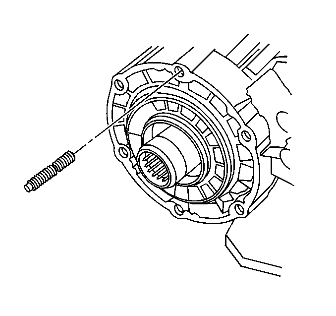
- Install the adapter studs to 29.5-30.5 mm (1.16-1.20 in) in height, if removed.
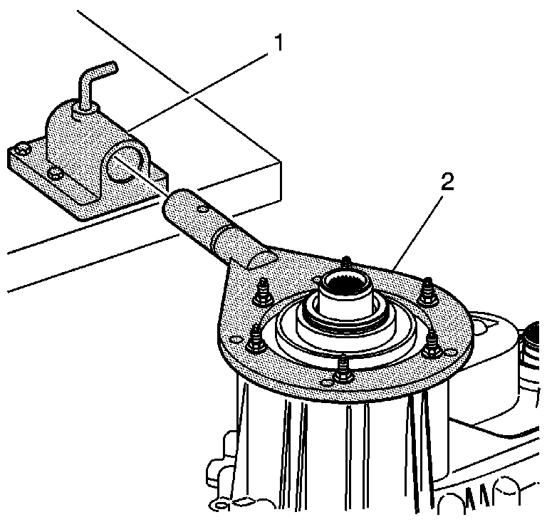
- Attach the
J 45759
to the front transfer case using the adapter studs. All of the assembly procedures can be performed with the case mounted to the
J 45759
.
- Install the
J 45759
(2) into the
J 3289-20
(1) and secure with the pivot pin.
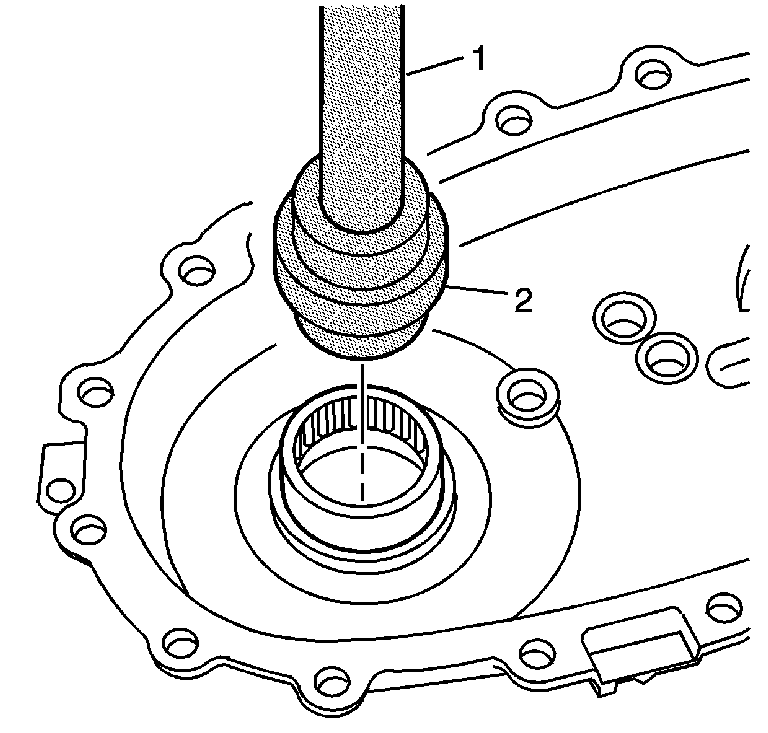
- Using the
J 8092
(1) and the
J 36370
(2), install the front output shaft rear bearing.
| • | The letters on the bearing face toward the tool. |
| • | Use the double shoulder side of the
J 36370
. |
| • | The install depth from the case shoulder is 1.4-1.6 mm (0.055-0.063 in). |
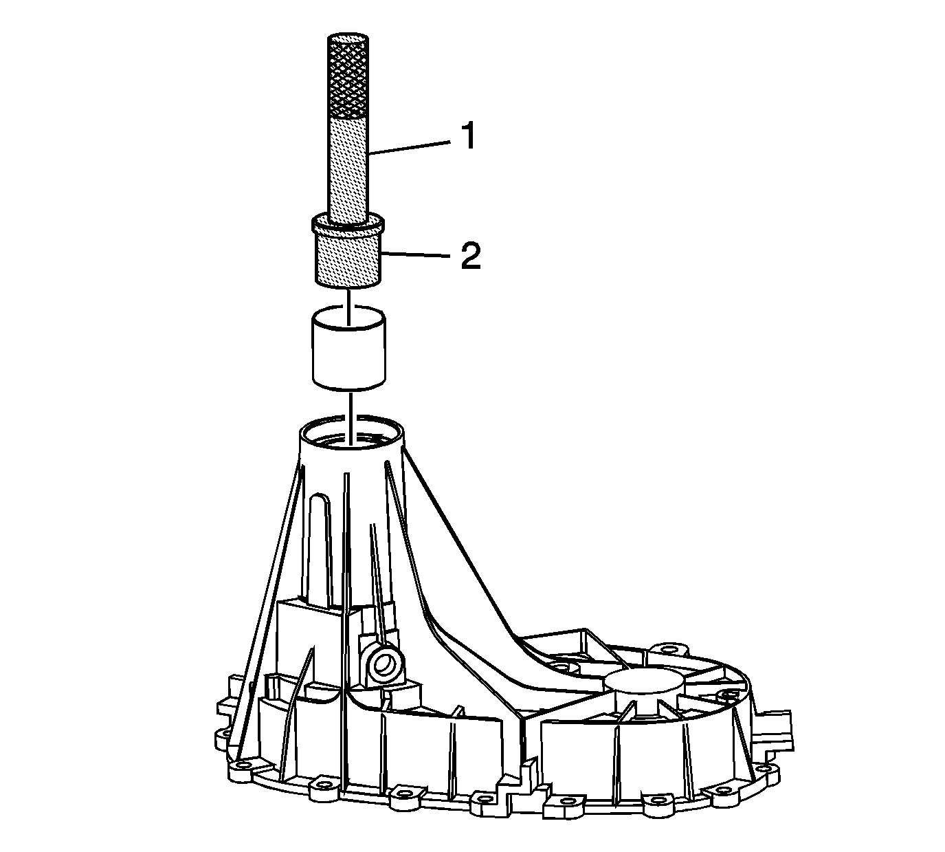
- SHD only - Install a new rear output shaft bushing, using the
J 8092
(1) and
DT-48022
(2).
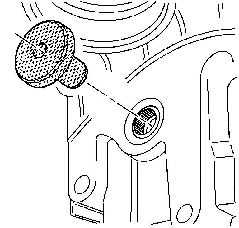
- Using the
J 42737
, install the shift detent lever shaft
bearing. The seal side of the bearing faces outward.
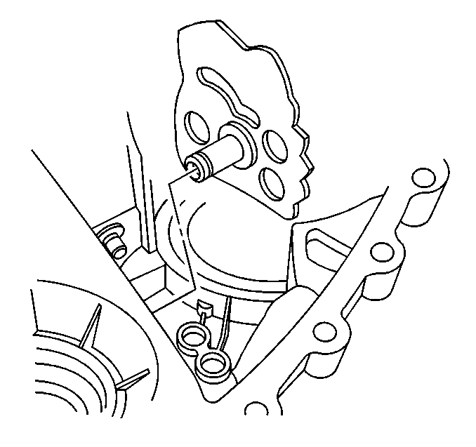
- Install the shift detent lever shaft.
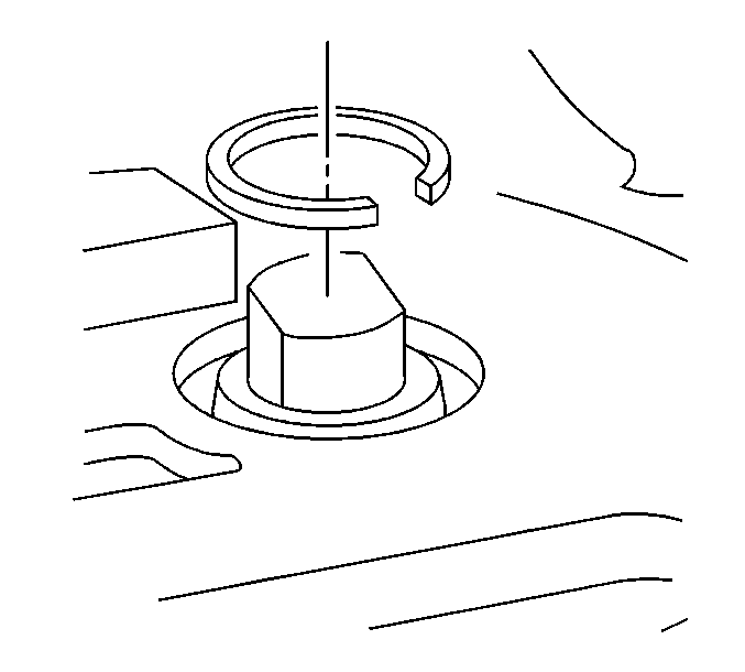
- Install the shift detent lever shaft retaining ring.
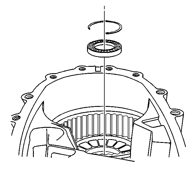
- For the non-super heavy duty (SHD) model, install the input gear bearing. The cage side of the bearing
faces forward.
- For the non-SHD model, install the input gear bearing inner retaining ring.
- For the SHD model, install the retaining ring for the input gear bearing.
Important: When installing the input gear bearing, ensure the groove in the input gear bearing is facing up.
- For the SHD model, expand the retaining ring and install the input gear bearing with the groove up.
- For the SHD model, fully seat the retaining ring in the bearing groove.
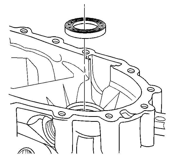
- Install the front output shaft front bearing. The cage side of the bearing faces forward.
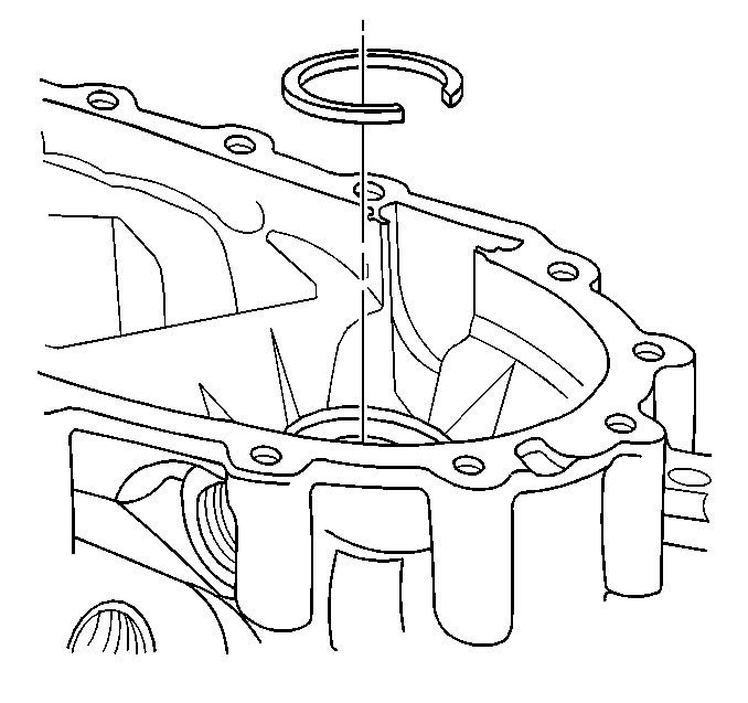
- Install the front output shaft front bearing inner retaining ring.
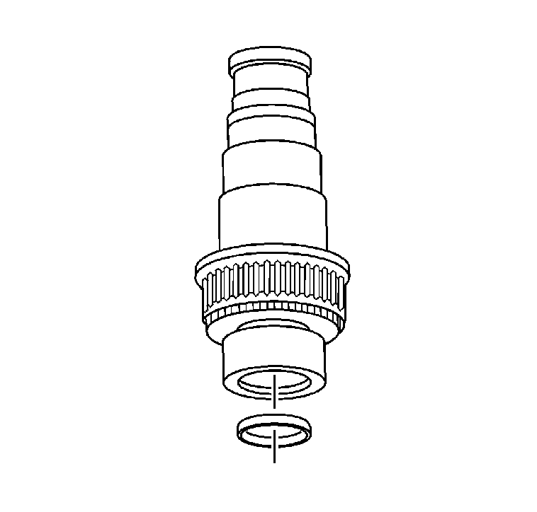
- If it is a new shaft, or if the cup plug was removed, install the cup plug in
the front output shaft, using a suitable driver. The installed depth of the cup plug is 26.75 mm (1.05 in) from the end of the shaft.
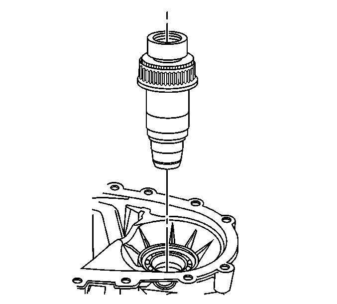
- Install the front output shaft assembly.
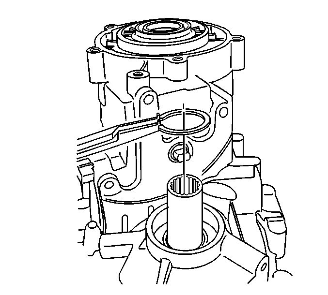
- Install the front output shaft front bearing outer retaining ring.
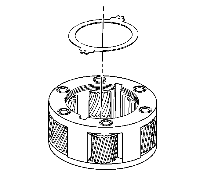
- Install the planetary carrier thrust washer.
The thrust washer with the tabs must be installed.
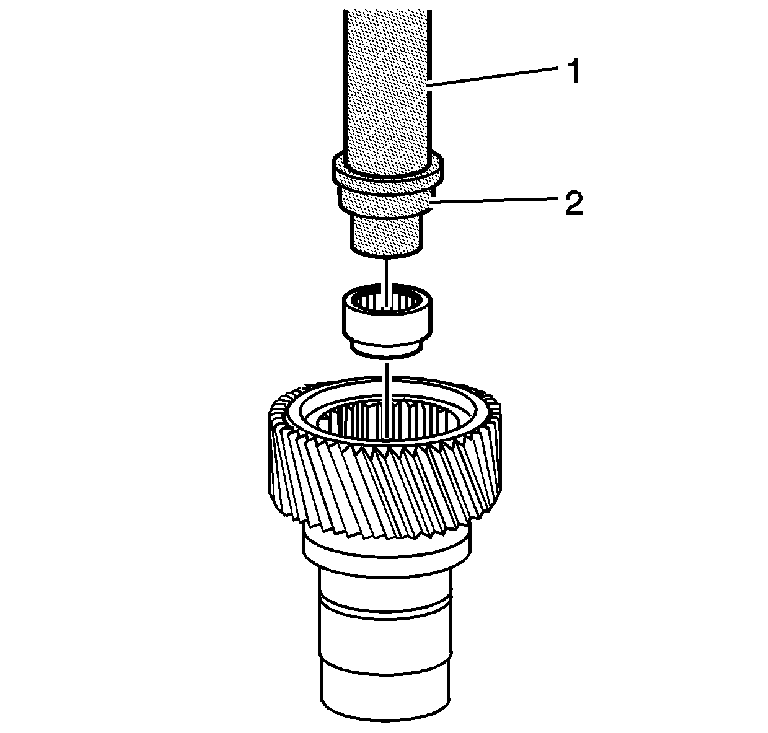
- Install the needle bearing in the input gear, using the
J 8092
(1) and the
J 45383
(2). Use the large diameter of the tool to install the bearing.
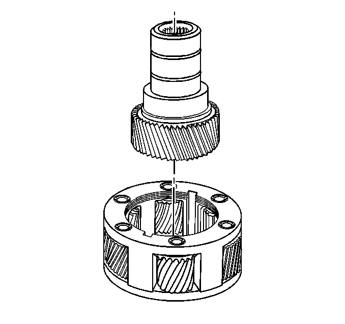
- Install the input gear in the planetary carrier.
- Ensure the input gear turns freely. If the input gear does not turn freely, inspect for debris.
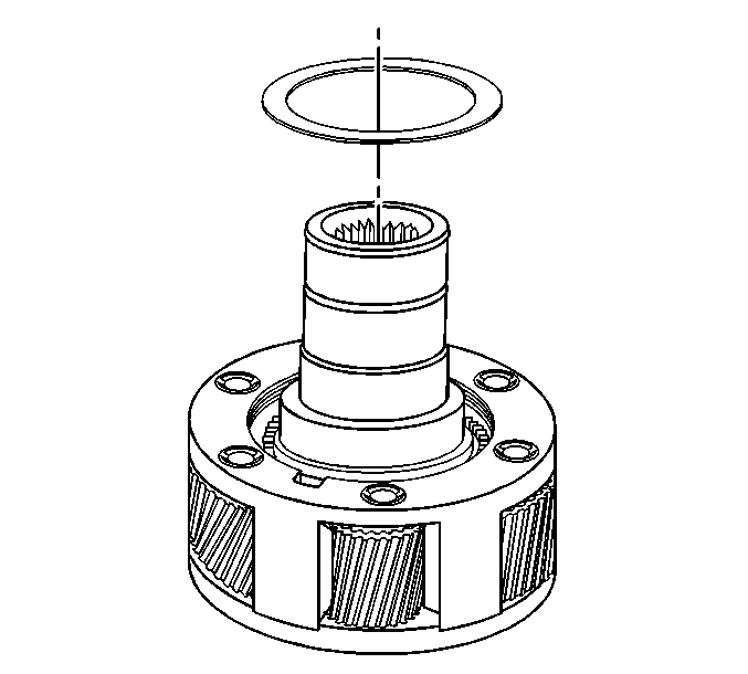
- Install the planetary carrier front thrust washer.
The thrust washer
without the tabs must be installed.
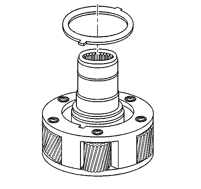
Important: If the lock plate has a stamped letter "E", ensure that the letter "E" stamped on the lock plate is facing up.
- Install the planetary carrier lock plate.
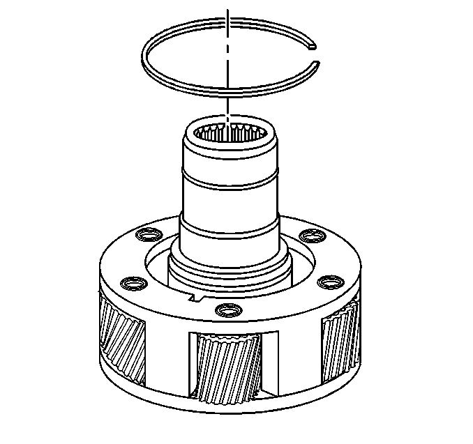
- Install the retaining ring for the input gear.
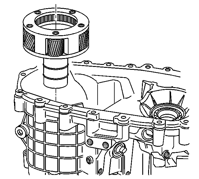
- Install the high/low planetary carrier.
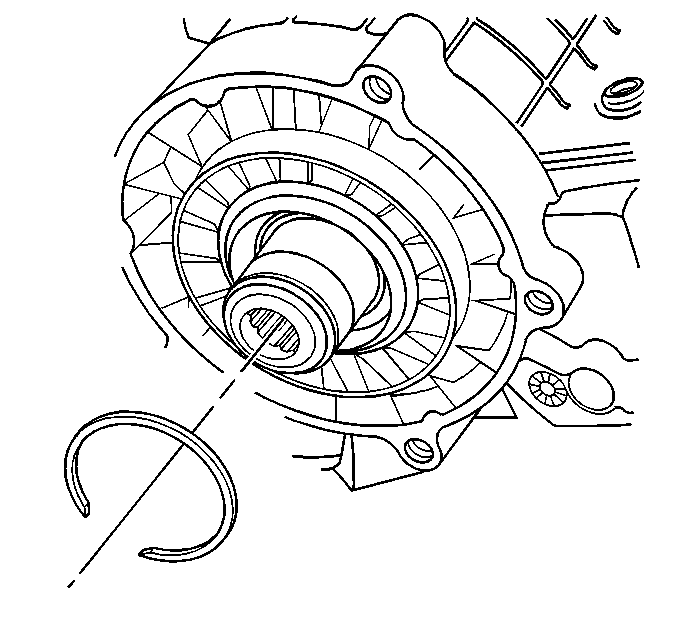
- Install the outer retaining ring for the input gear bearing.
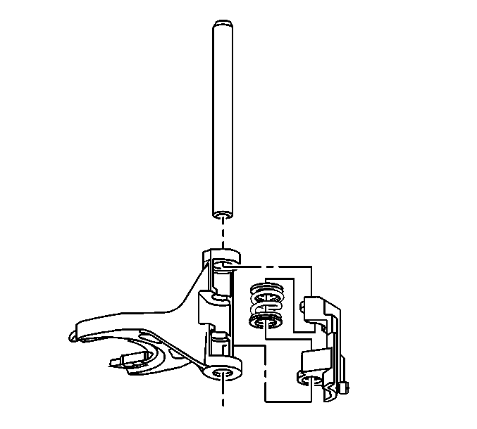
- Assemble the high/low shift fork assembly.
- Install the shift fork pads.
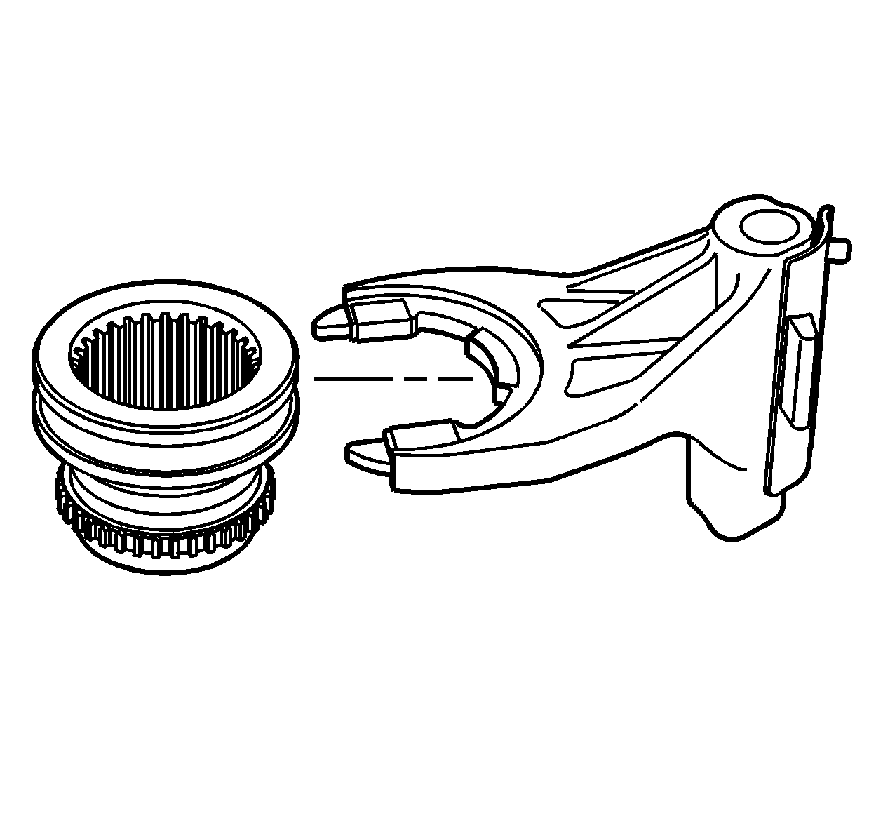
- Install the high/low shift fork on the high/low range sleeve.
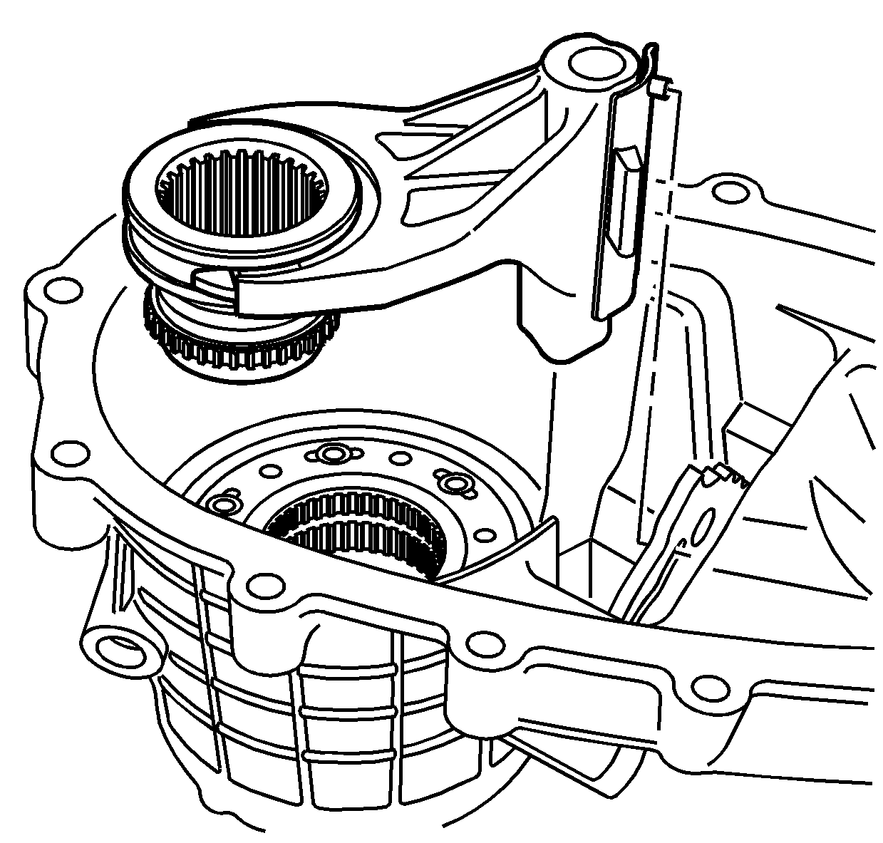
- Install the high/low range sleeve with the shift fork
to the planetary carrier.
- Position the shift fork pin in the shift detent lever slot.
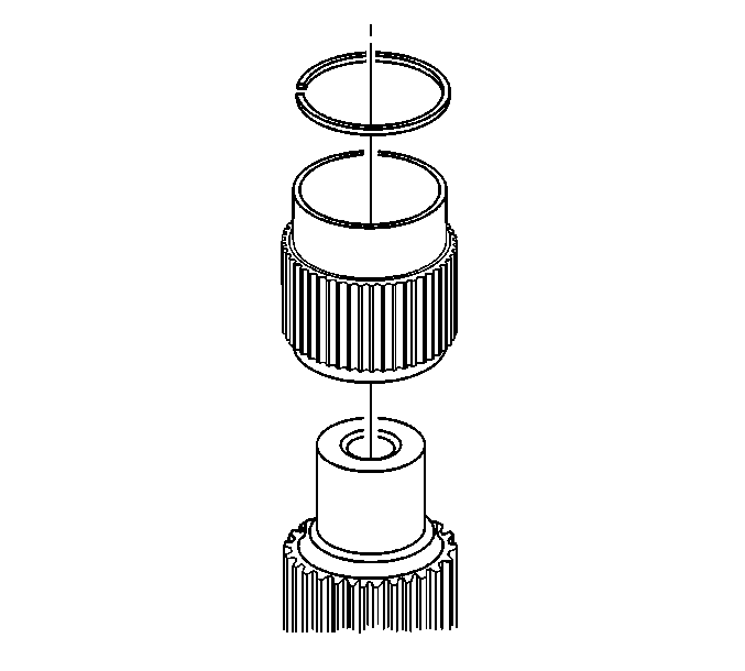
- Mount the rear output shaft in a soft-jaw vise with the input end up.
- Install the drive sprocket sleeve on the rear output shaft.
- Install the drive sprocket front retaining ring.
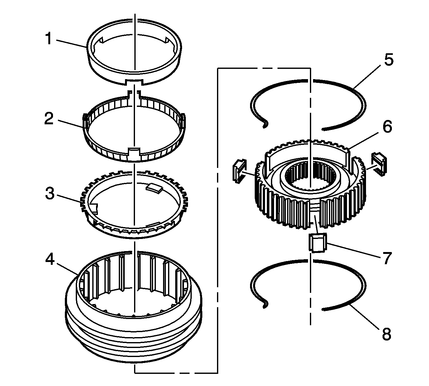
- If disassembled, assemble the synchronizer assembly.
| 36.1. | Install the inserts (7) in the hub (6). |
| 36.2. | Install the insert springs (5 and 8). |
| - | The hooked ends are opposite each other and not installed in the same insert. |
| - | Ensure the hooked end of the spring is located in an insert slot. |
| 36.3. | Install the synchronizer sleeve (4) on the synchronizer hub (6). The sleeve with the taper and groove end aligns to the shorter side teeth of the hub. |
Ensure the inserts (7) are aligned with the splines in the synchronizer
sleeve (4).
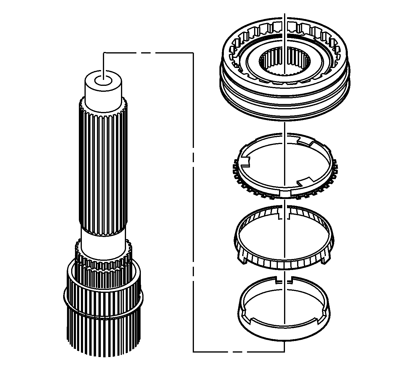
- Install the synchronizer rings on the rear output shaft. Align the tabs of the
outer ring with the slots in the inner ring.
| 37.1. | Install the inner ring. |
| 37.2. | Install the middle ring. |
| 37.3. | Install the outer ring. |
- Install the synchronizer assembly.
| • | The taper or groove end of the synchronizer sleeve faces toward the input end of the rear output shaft. |
| • | The outer synchronizer ring tabs align to the synchronizer hub. |
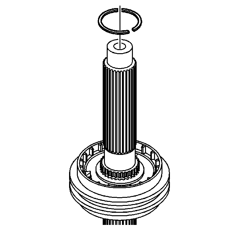
- Install the synchronizer retaining ring. Ensure the retaining ring is fully seated
in the groove.
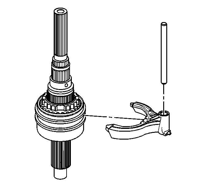
- Install the 2/4 wheel drive mode shift fork on the synchronizer assembly.
- Install the shift shaft in the mode shift fork.
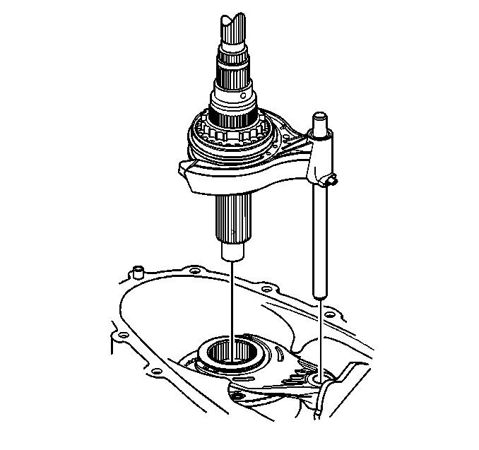
Important: Ensure the mode shift fork is installed with the roller side down.
- Install the shift shaft and the synchronizer assembly, with the rear output shaft, in the front case half and the high/low range sleeve.
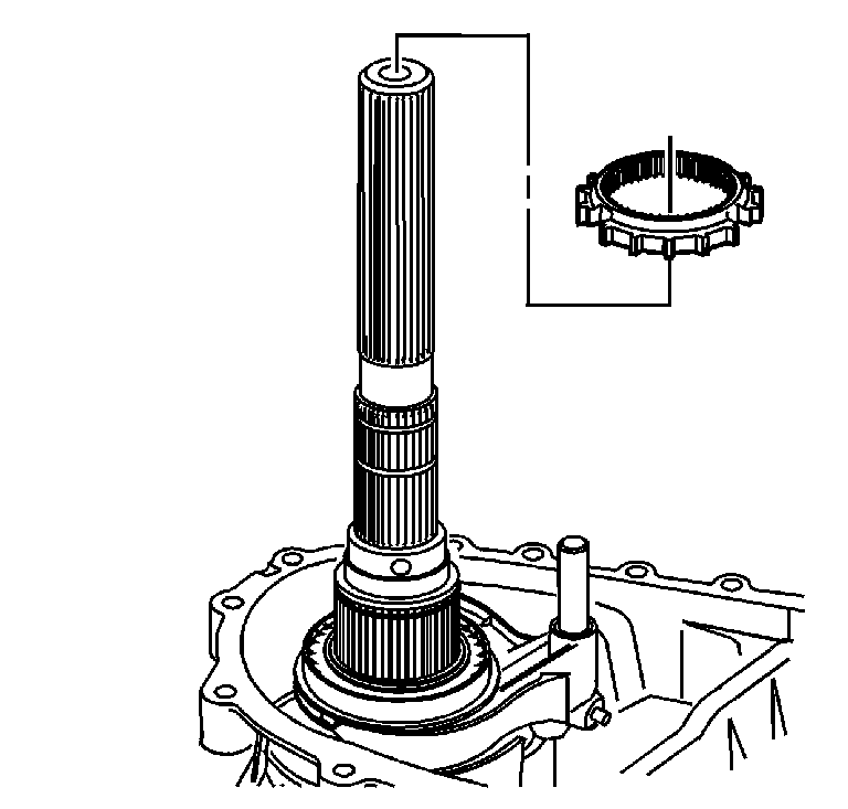
- Install the 2/4 wheel drive synchronizer gear.
| • | Ensure to align the middle synchronizer tabs to the gear. |
| • | Ensure the gear is aligned to the synchronizer sleeve. |
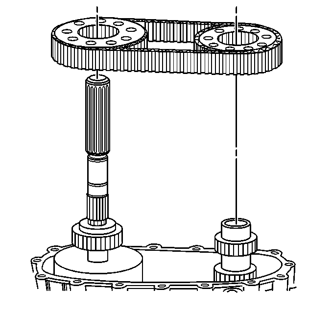
Important: When performing the following service procedure, ensure to align the marks of the drive chain and sprockets if using the chain and sprockets again.
- Install the drive chain on the front output shaft and the rear output shaft assembly.
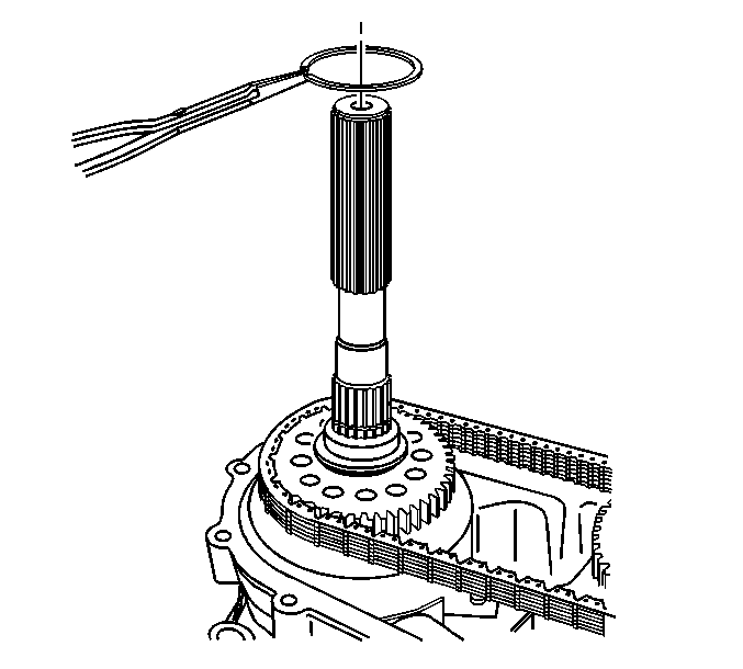
- Install the drive sprocket retaining ring.
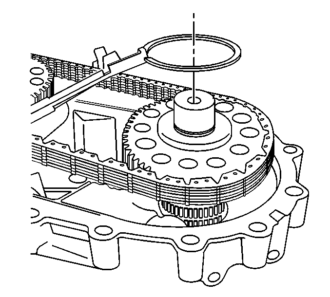
- Install the driven sprocket retaining ring.
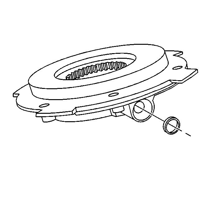
- Install a new oil pump O-ring, for the oil pump suction pipe, in the oil pump.
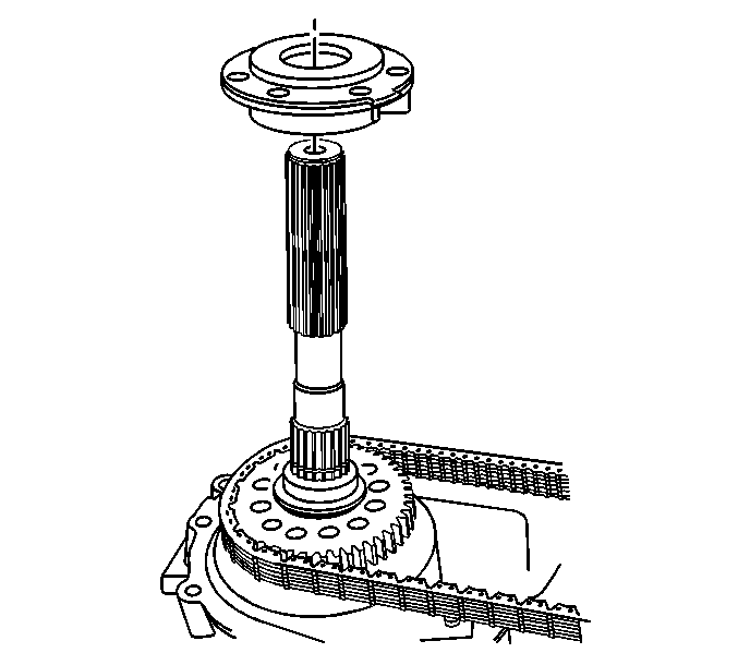
- Install the oil pump on the rear output shaft.
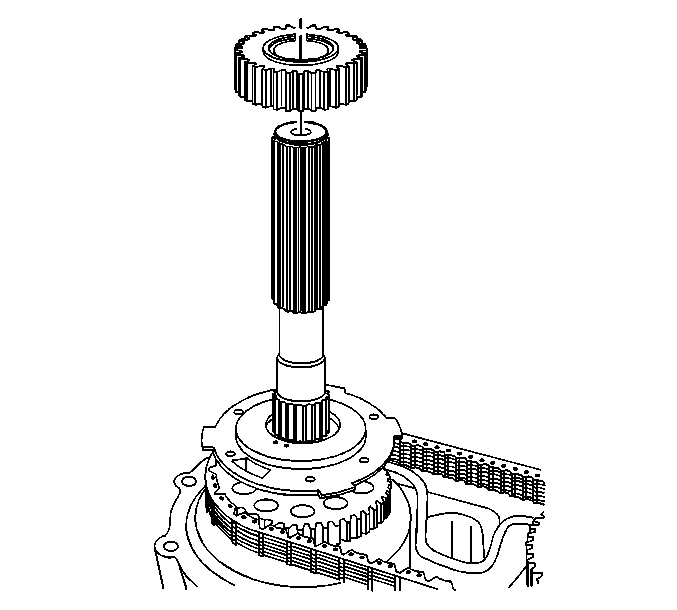
Important: Install the speed reluctor wheel with the step toward the oil pump assembly.
- Install the speed reluctor wheel.
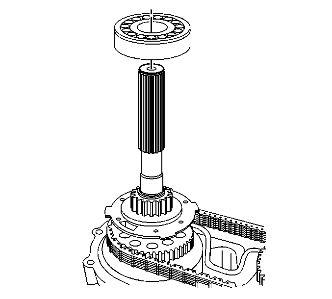
Important: When installing the rear output shaft bearing on the rear output shaft, ensure the groove on the rear output shaft bearing is facing up.
- Install the rear output shaft bearing.
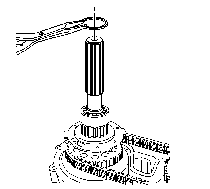
- Install a NEW rear output shaft bearing retaining ring.
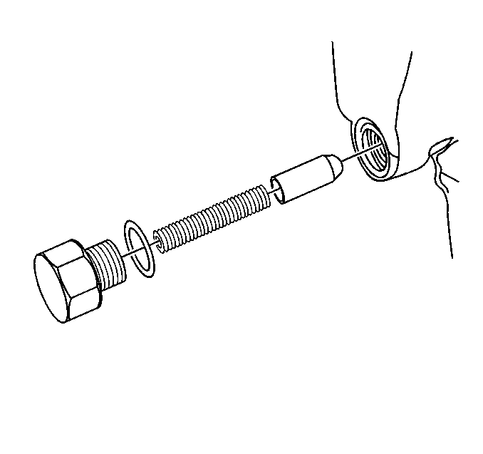
- Install a new O-ring seal on the shift detent spring bolt.
Notice: Refer to Fastener Notice in the Preface section.
- Install the shift detent spring, the plunger, and the bolt.
Tighten
Tighten the shift detent bolt to 17 N·m (13 lb ft).
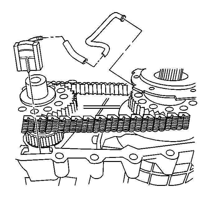
- Install the oil pump screen in the front case half.
- Install the connector on the oil pump screen.
- Install the oil pump suction pipe in the connector.
- Install the oil pump suction pipe in the oil pump body.
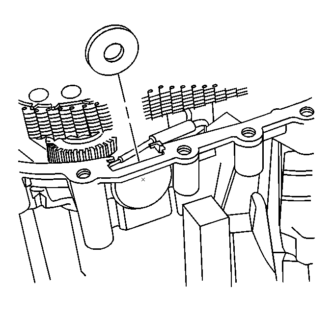
- Install the magnet.
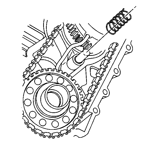
- Install the shift fork shaft spring on the shift shaft.
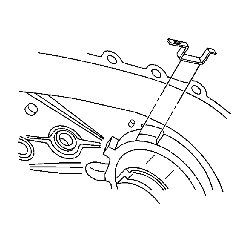
- Remove the 1st design oil pump wear sleeve from the rear case half.
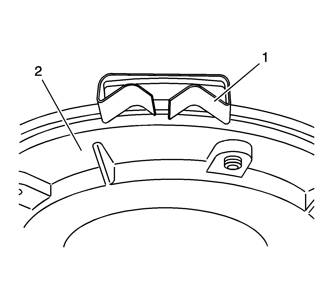
Important: Ensure the oil pump wear sleeve is properly positioned to the largest lug of the oil pump.
- Install the 2nd design oil pump wear sleeve (1) to the oil pump (2).
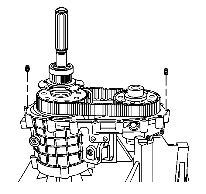
Important: Ensure the locating pins are installed in the front case half.
- Install the locating pins in the front case, if necessary.
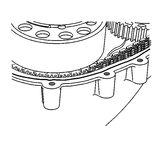
Notice: Apply the proper amount of sealant to the flange when assembling the transfer case. Excessive amounts of sealant can plug the oil pump screen, resulting in internal component failure.
Important: Ensure both sealing surfaces of the front and rear case halves are free of dirt, oil, and cleaning solvent.
- Apply a 3 mm (1/8 in) bead of RTV sealant GM P/N 12345739 (Canadian P/N 10953541) or equivalent to the front case half.
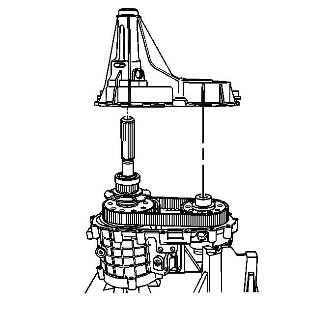
- Align the outer retaining ring tabs for the rear output shaft bearing with the slot in the rear case half.
- Install the rear case half to the front case half.
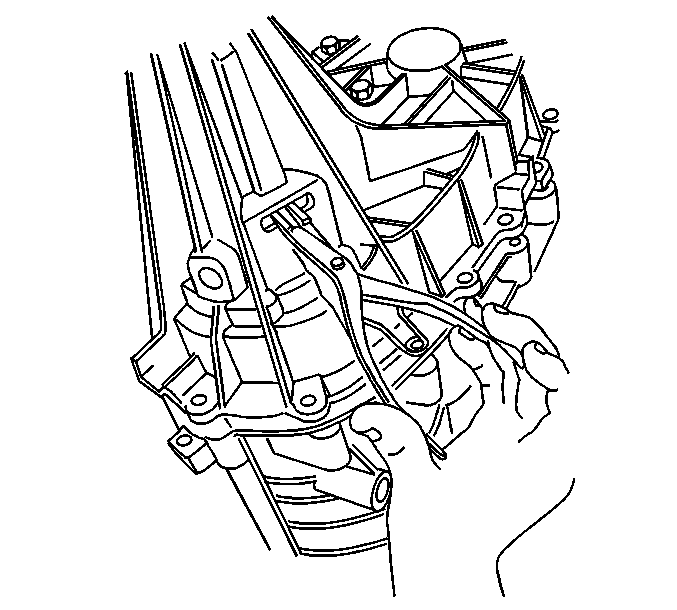
- Using snap ring pliers, open the outer retaining ring for the rear output shaft bearing.
- Insert a rubber coated screwdriver into the speed sensor hole.
- Lift up on the speed reluctor wheel then seat the retaining ring.
Notice: This component is made of magnesium. Proper assembly is required to
prevent damage. Ensure the magnesium transfer case housings are properly
insulated from all external steel components, or galvanic corrosion will occur.
New nylon coated case bolts and aluminum washers must be used. Use only aluminum
fill and drain plugs. Use only aluminum brackets under the case bolts. Ensure
new seals are installed that have a rubber insulated outside diameter and
have no tears or cuts. Extensive damage will occur if there is galvanic corrosion
between the magnesium and steel components.
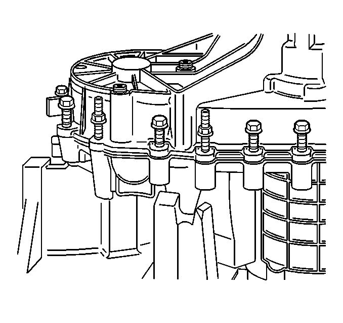
- Align the brackets to the proper bolt holes.
- Install the NEW case half bolts or studs and the aluminum washers.
Tighten
Tighten the case half bolts to 38 N·m (28 lb ft).
Important: The
J 45380
does not work on the SHD version of the transfer case.
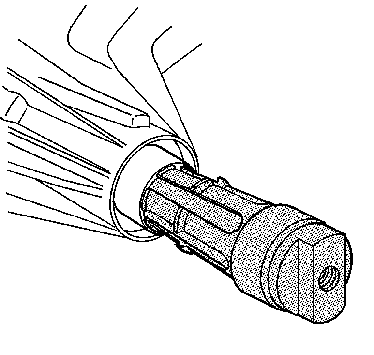
- LD and HD only - Install a new rear output shaft bushing, using the
J 45380
.
| 71.1. | Install the bushing on the finger section of the
J 45380
. |
| 71.2. | Install the finger section to the main body of the
J 45380
. |
| 71.3. | Position the bushing and tool to the case. |
| 71.4. | Using a hammer and the
J 45380
, install the bushing. |
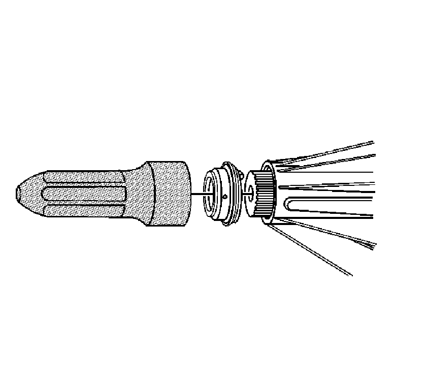
Important: When installing the rear output shaft seal, ensure that the drain hole is pointed down at an angle at which the transfer case would be installed in the vehicle.
- LD and HD only - Using the
J 37668-A
, install the rear output shaft seal to the transfer case.
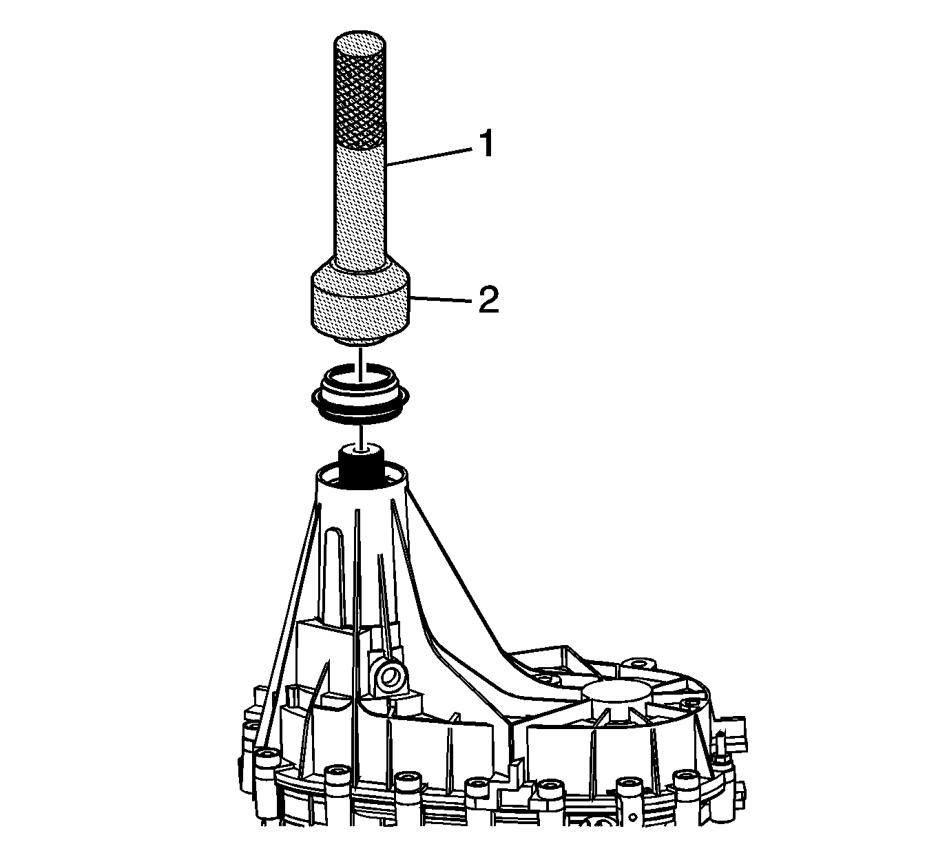
Important: When installing the rear output shaft seal, ensure that the drain hole is pointed down at an angle at which the transfer case would be installed in the vehicle.
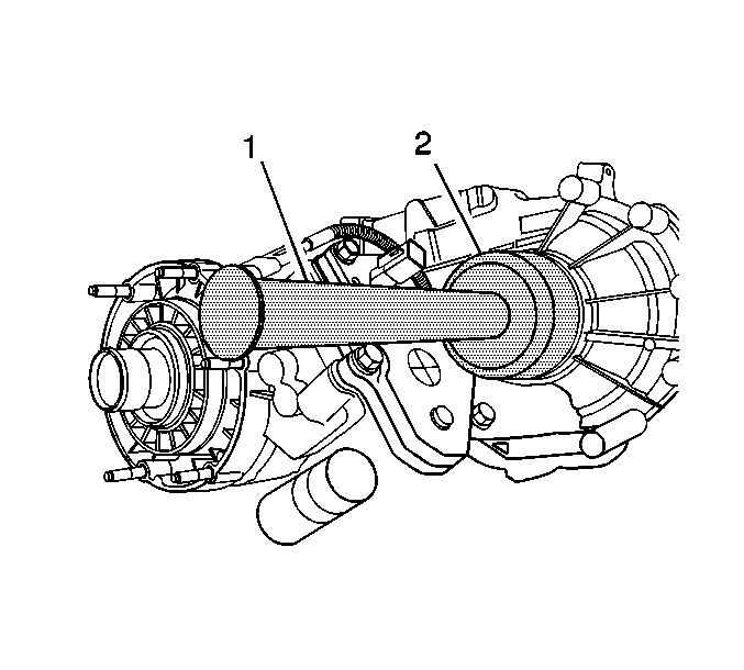
- SHD only - Using the
J 8092
(1) and
DT-48021
(2) , install the rear output shaft seal to the transfer case.
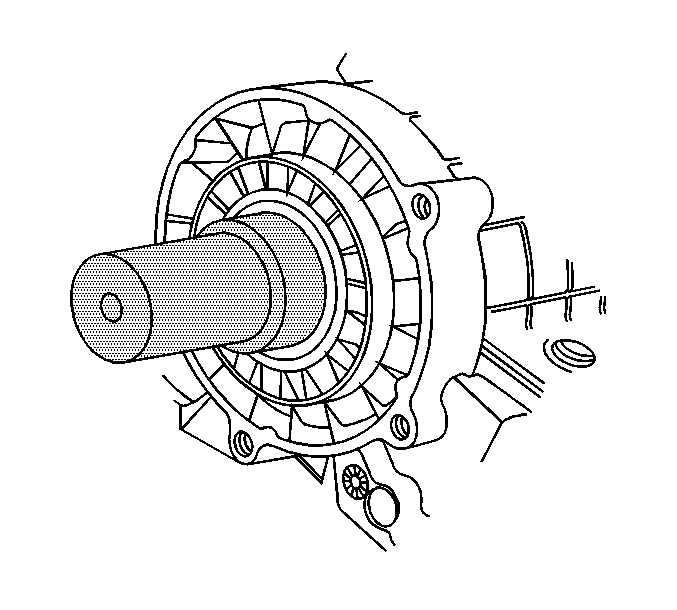
- Using the
J 43484
(2) and the
J 8092
(1), install the front output shaft seal in the transfer case.
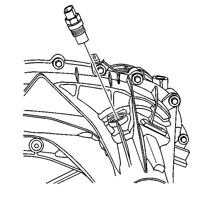
- Using the
J 42738
, install the input shaft seal to
the transfer case.
- Install a NEW O-ring seal on the vehicle speed sensor.
- Lubricate the vehicle speed sensor O-ring seal with transfer case fluid.
- Install the speed sensor in the transfer case.
Tighten
Tighten the speed sensor to 15 N·m (11 lb ft).
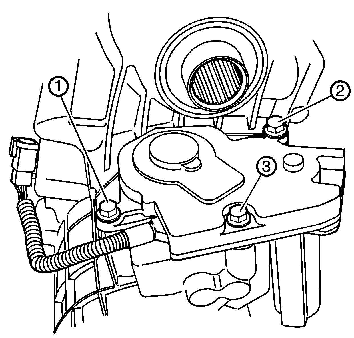
Important: A new encoder motor does not come with locating pins. Locating pins must be installed in the encoder motor for proper operation.
- Install the locating pins in the encoder motor.
- Install the actuator insulator gasket on the encoder motor.
- Install the encoder motor to the transfer case. Rotate the control actuator lever shaft to align to the encoder motor.
- Install the mounting bolts for the encoder motor.
Tighten
Tighten the encoder motor mounting bolts, in the sequence shown, to 20 N·m (15 lb ft).
- Install the case bolt for the wiring harness bracket.
Tighten
Tighten the case bolt to 38 N·m (28 lb ft).
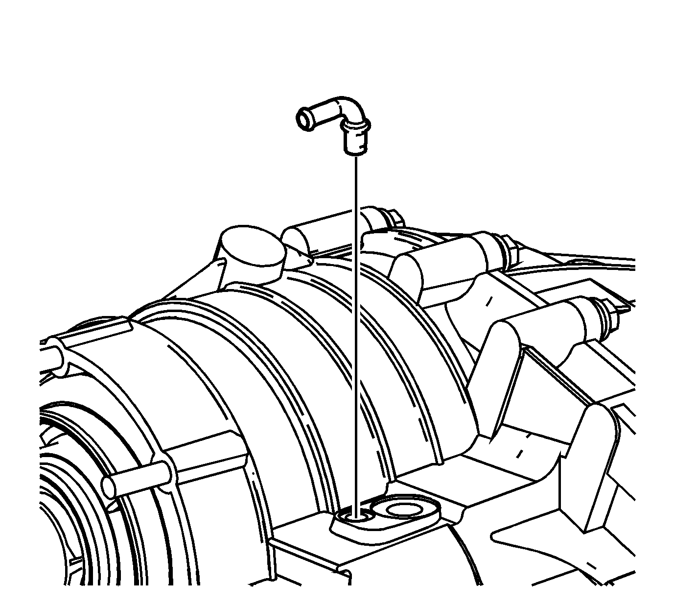
- Apply a thin layer of retaining compound GM P/N 12377901, Canadian P/N 10953504,
or equivalent, to the NEW aluminum vent pipe.
- Tap the NEW aluminum vent pipe into the case; ensure the vent pipe is aligned in the direction shown.
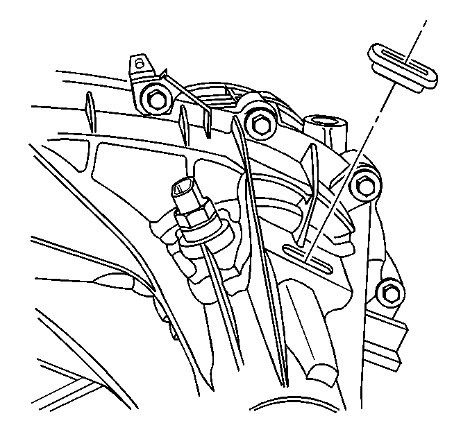
Important: Ensure that the correct access hole plug is used for the SHD model.
- Install the access hole plug in the transfer case.


