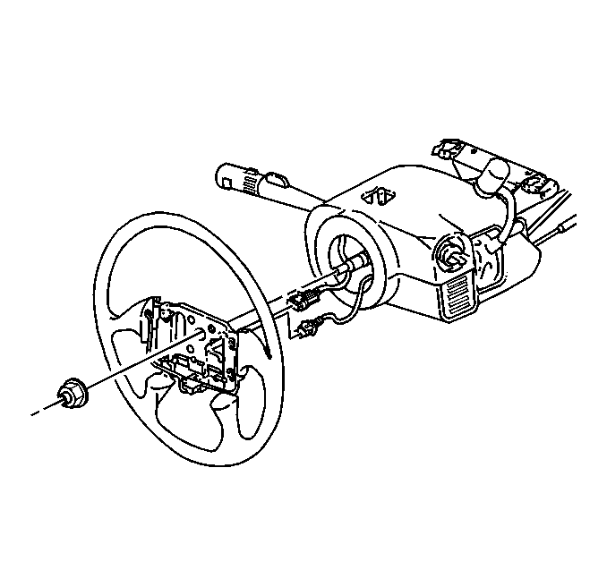
Tools Required
| • | J 1859-A Steering Wheel Puller |
| • | J 42578 Steering Wheel Puller Legs |
Removal Procedure
- Turn the ignition OFF.
- Disable the SIR system. Refer to SIR Disabling and Enabling in SIR.
- Remove the inflator module. Refer to Inflatable Restraint Steering Wheel Module Replacement in SIR.
- If there are no alignment mark on the steering wheel hub, scribe an alignment mark on the steering wheel hub in line with the mark on the steering shaft.
- Loosen the steering wheel nut.
- Position the steering wheel nut flush with the end of the steering column shaft.
- Loosen the steering wheel using the following tools:
- Disconnect the steering wheel controls electrical connector.
- Disconnect the horn switch lead from the steering hub.
- Remove the steering wheel nut.
- Remove the steering wheel from the steering shaft.
- If equipped, remove the controls and the controls harness from the steering wheel. Refer to Steering Wheel Control Switch Assembly Replacement .
Caution: Refer to SIR Caution in the Preface section.
| • | For Chevrolet and Oldsmobile vehicles, use J 1859-A . |
Installation Procedure
- If equipped install the controls and the controls harness to the steering wheel. Refer to Steering Wheel Control Switch Assembly Replacement .
- Route the SIR connector through the steering wheel.
- Align the mark on the steering wheel with the mark on the steering shaft.
- Install the steering wheel.
- Install the steering wheel nut.
- Connect the horn switch lead to the steering hub.
- Connect the steering wheel controls electrical connector.
- Install the inflator module. Refer to Inflatable Restraint Steering Wheel Module Replacement in SIR.
- Enable the SIR system. Refer to SIR Disabling and Enabling in SIR.
- Verify that the steering wheel controls operate properly.
- Verify that the horn operates properly.
Notice: Use the correct fastener in the correct location. Replacement fasteners must be the correct part number for that application. Fasteners requiring replacement or fasteners requiring the use of thread locking compound or sealant are identified in the service procedure. Do not use paints, lubricants, or corrosion inhibitors on fasteners or fastener joint surfaces unless specified. These coatings affect fastener torque and joint clamping force and may damage the fastener. Use the correct tightening sequence and specifications when installing fasteners in order to avoid damage to parts and systems.
Important: This is a prevailing torque type fastener. This fastener may be reused ONLY
if the following conditions are true:
• The fastener and its counterpart are clean and free from rust. • The fastener develops 3 N·m (27 lb in) of torque
against its counterpart prior to the fastener seating.
Tighten
Tighten the nut to 45 N·m (33 lb ft).
