Power Sliding Door Motor Clutch Replacement With RPO E58
Removal Procedure
- Disconnect the negative battery cable. Refer to Battery Negative Cable Disconnection and Connection in Engine Electrical.
- Remove the right rear quarter lower trim panel. Refer to Rear Quarter Trim Panel Replacement - Right Side in Interior Trim.
- Open the sliding door 1/3 of the way.
- Support the bottom of the sliding door.
- Remove the center roller bracket pin. Separate the center roller bracket, body side, from the center roller bracket, door side.
- Position the bottom of the sliding door out at the rear in order to provide access to the center roller bracket, body side.
- Remove the sliding door center track cover. Refer to Rear Side Door Center Track Cover Replacement .
- Position the sliding door center roller bracket, body side, at the front of the center roller track.
- Release the cable tension by pushing the tensioning nut inward. Pull the rear cable in order to achieve slack.
- Visually confirm that the cables are slack by observing that the center white dots are below the white indicator bands.
- Lift the center roller bracket, body side, up and out from the front radius of the sliding door center track.
- Detach the cable ends from the sliding door center roller bracket, body side.
- Remove the front pulley bolts.
- Remove the front pulley nut.
- Remove the front pulley from the front inner quarter panel.
- Remove the rear pulley bolts.
- Remove the rear cable from the opening at the rear of the sliding door center track.
- Remove the rear pulley from the rear inner quarter panel.
- Disconnect the wiring harness from the actuator control module.
- Remove the motor clutch assembly nuts.
- Remove the motor clutch assembly bolts.
- Carefully remove the motor clutch assembly from the vehicle.
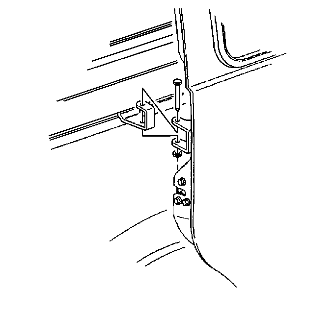
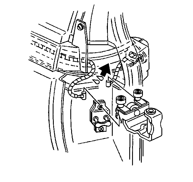
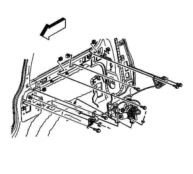
Notice: Use care when feeding cables to and from the center track and body to avoid damage to the coated cables and the vehicle's painted surface.
Installation Procedure
- Position the motor clutch assembly to the vehicle.
- Install the motor clutch assembly bolts.
- Install the motor clutch assembly nuts.
- Connect the wiring harness to the actuator control module.
- Route the rear cable through the opening in the rear sliding door center track.
- Position the rear pulley to the rear inner quarter panel.
- Install the rear pulley bolts.
- Route the front cable through the opening in the front inner quarter panel.
- Position the front pulley to the front inner quarter panel.
- Install the front pulley bolts.
- Install the front pulley nut.
- Connect both the front and rear ends of the motor clutch assembly cables to the center roller bracket.
- Install the center roller bracket to the center roller track.
- Carefully slide the center roller bracket to the front of the center roller track.
- Complete the following actions simultaneously:
- Position the center roller bracket at the front of the track. Ensure that the bracket is 25 mm (1 in) away from the forward radius, to the point where the tensioning slot is accessible in the window.
- Insert a 3/8 inch drill bit into the tension slot on the motor clutch assembly until the drill bit bottoms.
- Adjust the cable tension. Refer to Rear Side Door Actuator Cable Tension Adjustment .
- Remove the 3/8 inch drill bit from the cable tension slot.
- Install the sliding door center track cover. Refer to Rear Side Door Center Track Cover Replacement .
- Position the sliding door center roller bracket to the rear of the track. Align the pin holes.
- Install the pin to the sliding door center roller bracket.
- Remove the support from the power sliding door.
- Manually open and close the sliding door in order to verify that:
- Connect the negative battery cable. Refer to Battery Negative Cable Disconnection and Connection in Engine Electrical.
- Perform the reinitialization procedure. Refer to Power Sliding Door (PSD) Re-Initialization .
- Install the right rear quarter lower trim panel. Refer to Rear Quarter Trim Panel Replacement - Right Side in Interior Trim.

Notice: Use the correct fastener in the correct location. Replacement fasteners must be the correct part number for that application. Fasteners requiring replacement or fasteners requiring the use of thread locking compound or sealant are identified in the service procedure. Do not use paints, lubricants, or corrosion inhibitors on fasteners or fastener joint surfaces unless specified. These coatings affect fastener torque and joint clamping force and may damage the fastener. Use the correct tightening sequence and specifications when installing fasteners in order to avoid damage to parts and systems.
Tighten
Tighten the bolts to 10 N·m (89 lb in).
Tighten
Tighten the nuts to 10 N·m (89 lb in).
Notice: Use care when feeding cables to and from the center track and body to avoid damage to the coated cables and the vehicle's painted surface.
Tighten
Tighten the bolts to 10 N·m (89 lb in).
Tighten
Tighten the bolts to 10 N·m (89 lb in).
Tighten
Tighten the nut to 10 N·m (89 lb in).

Important: Ensure that the power sliding door cable barrels are properly installed into the sliding door center roller bracket, body side, cable retaining fingers located on the roller bracket. Then bend the retaining fingers 90 degrees over the barrel ends.
| • | Pull on the rear cable in order to apply temporary tension. |
| • | Pull the sliding door center roller bracket towards the front of the sliding door center track. |

| • | Latch/unlatch function operates |
| • | Cable assembly is correctly positioned in the center track |
| • | The door fits |
Power Sliding Door Motor Clutch Replacement With RPO E59
Removal Procedure
- Disconnect the negative battery cable. Refer to Battery Negative Cable Disconnection and Connection in Engine Electrical.
- Remove the left rear quarter lower trim panel. Refer to Rear Quarter Trim Panel Replacement - Right Side in Interior Trim.
- Open the left sliding door 1/3 of the way.
- Support the bottom of the left sliding door.
- Remove the center roller bracket pin. Separate the center roller bracket, body side, from the center roller bracket, door side.
- Position the bottom of the sliding door out at the rear in order to provide access to the center roller bracket, body side.
- Position the sliding door center roller bracket, body side, at the front of the center roller track.
- Release the cable tension. Refer to Rear Side Door Actuator Cable Tension Adjustment .
- Lift the center roller bracket, body side, up and out from the front radius of the sliding door center track.
- Detach the cable ends from the sliding door center roller bracket, body side.
- Remove the sliding door center track cover. Refer to Rear Side Door Center Track Cover Replacement .
- Slide the cable guide bracket pulley cover off of the pulley.
- Lift the rear cable off of the cable guide bracket pulley.
- Remove the cable guide bracket pulley screws.
- Remove the cable guide bracket pulley from the vehicle.
- Remove the rear cable from the opening at the rear of the sliding door track.
- Rotate the rear cable housing 90 degrees in order to unlock the rear cable housing from the body.
- Remove the rear air distribution ducts if equipped. Refer to Auxiliary Air Distributor Duct Replacement in Heating, Ventilating and Air Conditioning.
- Remove the front pulley bolts.
- Remove the front pulley from the left front inner quarter panel.
- Disconnect the electrical harness from the power sliding door actuator control module.
- Remove the motor clutch assembly nuts.
- Remove the motor clutch assembly bolts.
- Carefully remove the motor clutch assembly from the vehicle.


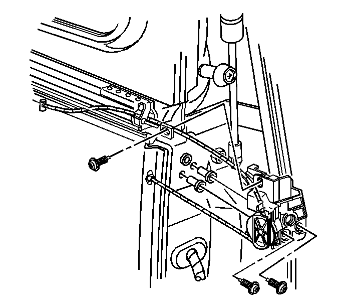
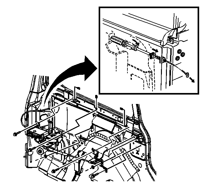
Notice: Use care when feeding cables to and from the center track and body to avoid damage to the coated cables and the vehicle's painted surface.
Installation Procedure
- Position the motor clutch assembly to the vehicle.
- Install the motor clutch assembly bolts.
- Install the motor clutch assembly nuts.
- Route the front cable through the body.
- Position the front pulley to the front inner quarter panel.
- Install the front pulley bolts.
- Install the rear cable through the opening in the rear pillar.
- Rotate the end of the rear cable housing 90 degrees in order to lock the housing into place. Start with the flat edges outward against the quarter panel. Observe the forward locking tab in order to judge the position of the rearward locking tab. This ensures that the flat side of the locking clips are properly positioned.
- Connect the electrical harness to the power sliding door actuator control module.
- Install the rear air distribution ducts if equipped. Refer to Auxiliary Air Distributor Duct Replacement in Heating, Ventilation and Air Conditioning.
- Position the cable guide bracket pulley to the rear pillar.
- Install the cable guide bracket pulley bolts
- Route the rear cable through the guide bracket pulley.
- Slide the cable guide bracket pulley cover over the pulley.
- Align the slot in the cable guide bracket pulley cover to the hole in the guide bracket.
- Connect both the front and rear cable ends to the center roller bracket.
- Install the center roller bracket to the center roller track.
- Position the sliding door roller bracket in front of the sliding door center track.
- Adjust the cable tension. Refer to Rear Side Door Actuator Cable Tension Adjustment .
- Install the sliding door center track cover. Refer to Rear Side Door Center Track Cover Replacement .
- Position the sliding door center roller bracket to the rear of the track. Align the pin holes.
- Install the pin to the sliding door center roller bracket.
- Remove the support from the sliding door.
- Manually open and close the sliding door in order to verify the following:
- Connect the negative battery cable. Refer to Battery Negative Cable Disconnection and Connection in Engine Electrical.
- Perform the reinitialization procedure. Refer to Power Sliding Door (PSD) Re-Initialization .
- Install the right rear quarter lower trim panel. Refer to Rear Quarter Trim Panel Replacement - Right Side in Interior Trim.

Notice: Use the correct fastener in the correct location. Replacement fasteners must be the correct part number for that application. Fasteners requiring replacement or fasteners requiring the use of thread locking compound or sealant are identified in the service procedure. Do not use paints, lubricants, or corrosion inhibitors on fasteners or fastener joint surfaces unless specified. These coatings affect fastener torque and joint clamping force and may damage the fastener. Use the correct tightening sequence and specifications when installing fasteners in order to avoid damage to parts and systems.
Tighten
Tighten the bolts to 10 N·m (89 lb in).
Tighten
Tighten the nuts to 10 N·m (89 lb in).
Notice: Use care when feeding cables to and from the center track and body to avoid damage to the coated cables and the vehicle's painted surface.
Tighten
Tighten the bolts to 10 N·m (89 lb in).

Tighten
Tighten the pulley bolts to 10 N·m (89 lb in).

Important: Ensure that the power sliding door cable barrels are properly installed into the sliding door center roller bracket, body side, cable retaining fingers located on the roller bracket. Then bend the retaining fingers 90 degrees over the barrel ends.

| • | The latch/unlatch function operates. |
| • | The cable assembly is correctly positioned in the center track. |
| • | The door fits properly. |
