Tools Required
J 38185 Hose Clamp Pliers
Removal Procedure
Caution: An electric fan under the hood can start up even when the engine is not running and can injure you. Keep hands, clothing and tools away from any underhood electric fan.
Caution: To help avoid personal injury or damage to the vehicle, a bent, cracked, or damaged fan blade or housing should always be replaced.
- Disconnect the negative battery cable. Refer to Battery Negative Cable Disconnection and Connection in Engine Electrical.
- Remove the air cleaner and duct assembly. Refer to Air Cleaner Assembly Replacement in Engine Controls - 3.4L.
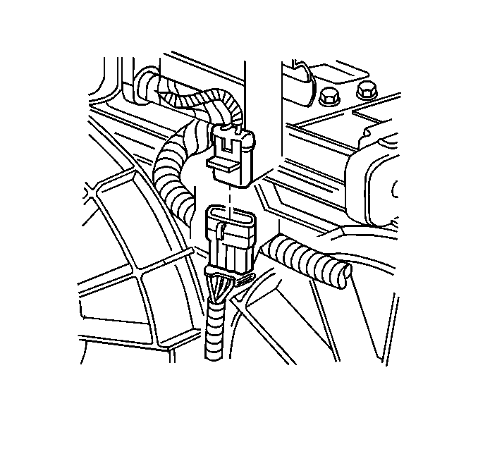
- Disconnect the cooling fan harness electrical connector.
- Remove right side diagonal brace. Refer to Front End Sheet Metal Diagonal Brace Replacement - Right Side in Body Front End.
- Loosen the engine mount strut nuts engine side.
- Remove the engine mount strut bracket brace bolts from the upper radiator support and rotate the struts and brackets rearward.
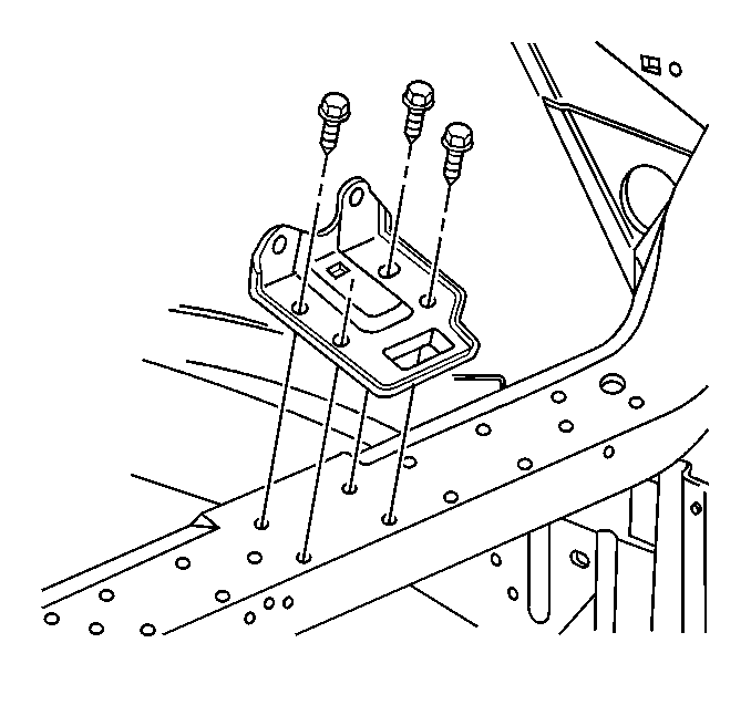
- Remove hood latch support bolts.
- Reposition hood latch support.
- Remove upper radiator hose. Refer to Radiator Inlet Hose Replacement .
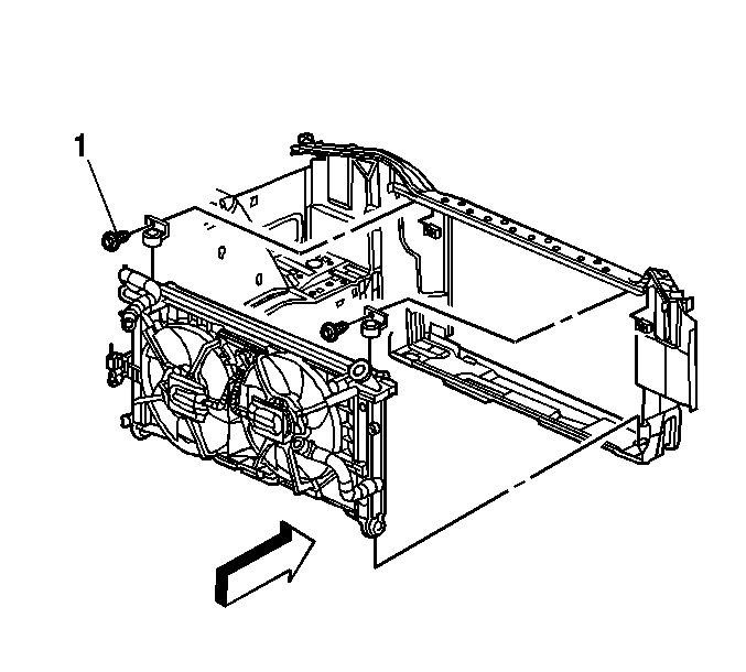
- Remove the radiator upper mount bolts (1).
- Remove the radiator upper mounts.
- Disconnect the relay mounting clip and reposition relay and harness aside.
- Remove the cooling fan shroud bolts.
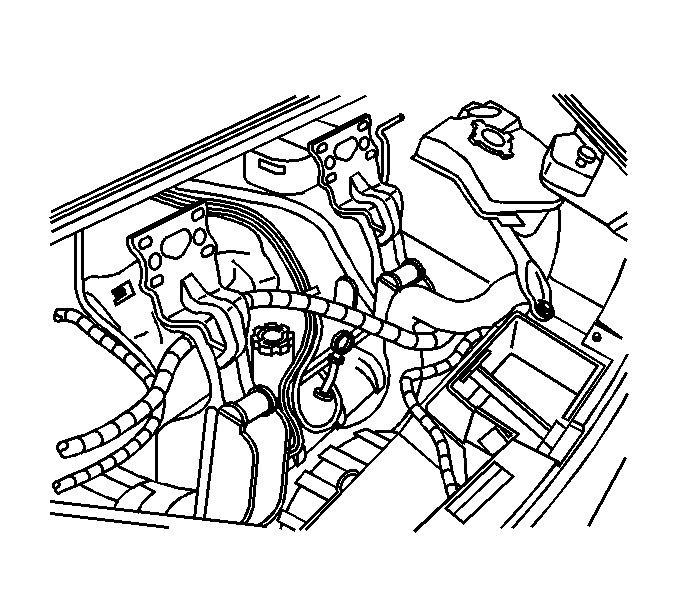
- Reposition the coolant overflow hose clamp at the radiator using the J 38185 .
- Disconnect and reposition the coolant overflow hose.
- Disconnect the upper transmission oil cooler (TOC) line from the radiator. Refer to Transmission Fluid Cooler Hose/Pipe Quick-Connect Fitting Disconnection and Connection in Automatic Transaxle - 4T65-E.
- Disconnect the TOC lines from the fan module retainer clip.
- Remove the cooling fans with the cooling fan shroud.


Installation Procedure
- Install the cooling fans with the cooling fan shroud.
- Connect the TOC lines to the fan module retainer clip.
- Connect the upper TOC line to the radiator. Refer to Transmission Fluid Cooler Hose/Pipe Quick-Connect Fitting Disconnection and Connection in Automatic Transaxle - 4T65-E.
- Install the cooling fan shroud bolts.
- Connect the relay mounting clip.
- Install the radiator upper mounts.
- Install the radiator upper mount bolts (1).
- Install the coolant overflow hose to the radiator.
- Reposition the hose clamp to secure the coolant overflow hose using theJ 38185 .
- Install the upper radiator hose. Refer to Radiator Inlet Hose Replacement .
- Position hood latch support on the upper radiator support.
- Install the hood latch support bolts.
- Position the engine mount struts brackets flush with the upper radiator support.
- Install the engine mount strut bracket brace bolts to the upper radiator support.
- Tighten the engine strut mount nuts engine side.
- Install right side diagonal brace. Refer to Front End Sheet Metal Diagonal Brace Replacement - Right Side in Body Front End.
- Connect the cooling fan harness electrical connector.
- Install the air cleaner and duct assembly. Refer to Air Cleaner Assembly Replacement in Engine Controls - 3.4L.
- Connect the negative battery cable. Refer to Battery Negative Cable Disconnection and Connection in Engine Electrical.

Notice: Use the correct fastener in the correct location. Replacement fasteners must be the correct part number for that application. Fasteners requiring replacement or fasteners requiring the use of thread locking compound or sealant are identified in the service procedure. Do not use paints, lubricants, or corrosion inhibitors on fasteners or fastener joint surfaces unless specified. These coatings affect fastener torque and joint clamping force and may damage the fastener. Use the correct tightening sequence and specifications when installing fasteners in order to avoid damage to parts and systems.
Tighten
Tighten the bolts to 6 N·m (53 lb in).
Tighten
Tighten the bolts to 10 N·m (88 lb in).

Tighten
Tighten the bolts to 25 N·m (18 lb ft).

Tighten
Tighten bolts to 28 N·m (21 lb ft).
Tighten
Tighten the nuts to 48 N·m (35 lb ft).

