Removal Procedure
Tools Required
Notice: Wheel drive shaft boots, seals and clamps should be protected
from sharp objects any time service is performed on or near the wheel drive
shaft(s). Damage to the boot(s), the seal(s) or the clamp(s) may cause lubricant
to leak from the joint and lead to increased noise and possible failure
of the wheel drive shaft.
- Raise and support the vehicle. Refer to
Lifting and Jacking the Vehicle
in General Information.
- Remove the tire and wheel. Refer to
Tire and Wheel Removal and Installation
in Tires and Wheels.
- Remove the stabilizer shaft link. Refer to
Stabilizer Shaft Link Replacement
in Front Suspension.
- Remove the tie rod end from the steering knuckle. Refer to
Rack and Pinion Outer Tie Rod End Replacement
in Power Steering System.
- Disconnect the lower ball joint from the steering knuckle. Refer
to
Lower Control Arm Replacement
in Front Suspension.
- Insert a drift or a flat-bladed tool through the brake caliper
hole and into the brake rotor in order to prevent the rotor from rotating.

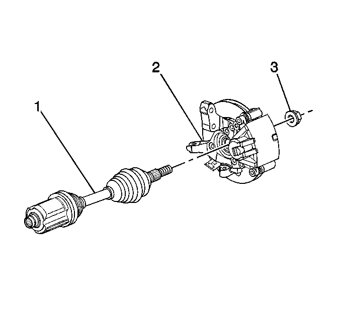
- Remove the drive axle
nut (3).

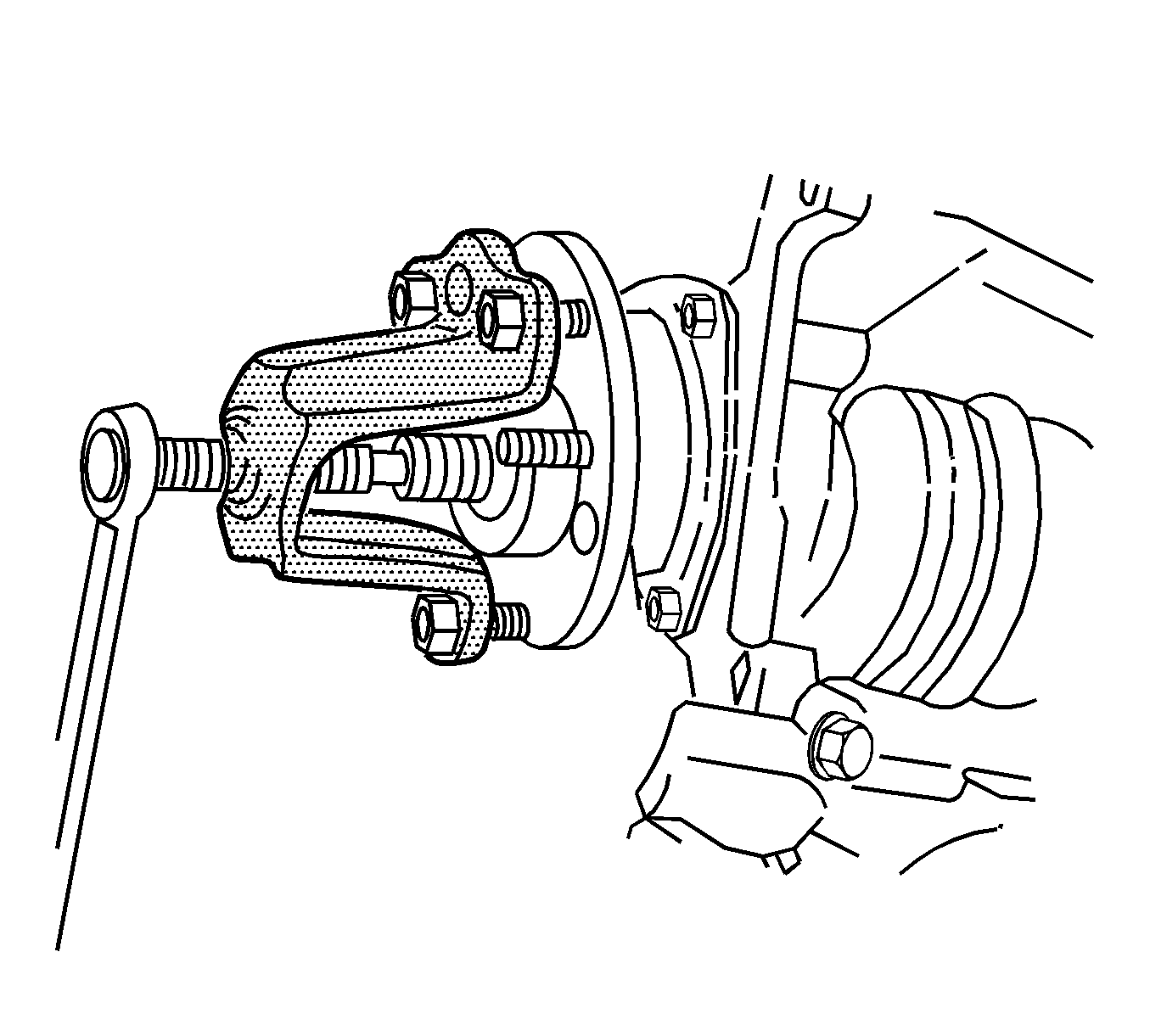
- Use the J 28733-B
in order to remove the drive axle
from the wheel bearing/hub.

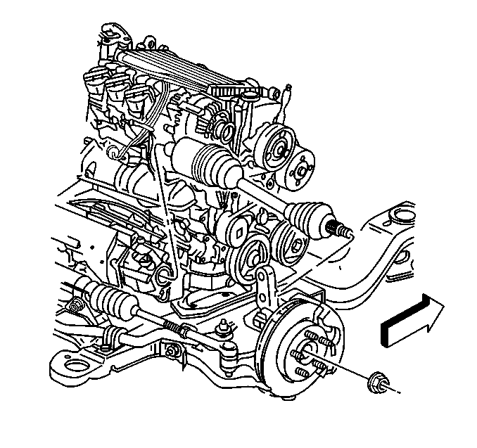
- Use the J 33008
, the J 29794
and the J 2619-01
in order to remove the right drive axle from the transaxle.
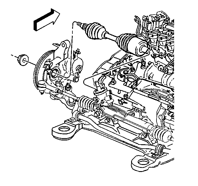
- Insert a large, flat-bladed tool between the left side lower control
arm and the frame.
- Insert the tip (end) of the flat-bladed tool into the groove on
the drive axle tripot joint.
- Use the flat-bladed tool in order to pry the left drive axle from
the transaxle.

Notice: Do not overextend the wheel drive shaft. Allowing the inboard joint
to overextend can cause separation of the internal components and lead to
joint failure.
- Remove the left drive axle.
Installation Procedure

- Install the left drive
axle.
- Ensure that the drive axle is installed properly.
| 2.1. | Push the drive axle into the transaxle until it snaps in place. |
| 2.2. | Grasp the tripot (inner) joint housing. |
| 2.3. | Pull on the tripot (inner) joint housing in order to verify that
the retaining ring is engaged. |
Do NOT pull on the drive axle shaft.

- Install the right drive
axle.
- Ensure that the drive axle is installed properly.
| 4.1. | Push the drive axle into the transaxle until it snaps in place. |
| 4.2. | Grasp the tripot (inner) joint housing. |
| 4.3. | Pull on the tripot (inner) joint housing in order to verify that
the retaining ring is engaged. |
Do NOT pull on the drive axle shaft.

- Install the drive axle (1)
into the wheel bearing.
- Insert a drift or a flat-bladed tool through the brake caliper
hole and into the brake rotor in order to prevent the rotor from rotating.
Notice: Use the correct fastener in the correct location. Replacement fasteners
must be the correct part number for that application. Fasteners requiring
replacement or fasteners requiring the use of thread locking compound or sealant
are identified in the service procedure. Do not use paints, lubricants, or
corrosion inhibitors on fasteners or fastener joint surfaces unless specified.
These coatings affect fastener torque and joint clamping force and may damage
the fastener. Use the correct tightening sequence and specifications when
installing fasteners in order to avoid damage to parts and systems.
- Install the NEW
drive axle nut (3).
Tighten
Tighten the nut to 160 N·m (118 lb ft).
- Install the ball joint to the steering knuckle. Refer to
Lower Control Arm Replacement
in Front Suspension.
- Install the tie rod end to the steering knuckle. Refer to
Rack and Pinion Outer Tie Rod End Replacement
in Power Steering System.
- Install the stabilizer shaft link. Refer to
Stabilizer Shaft Link Replacement
in Front Suspension.
- Install the tire and wheel. Refer to
Tire and Wheel Removal and Installation
in Tires and Wheels.
- Lower the vehicle.


