Removal Procedure
Tools Required
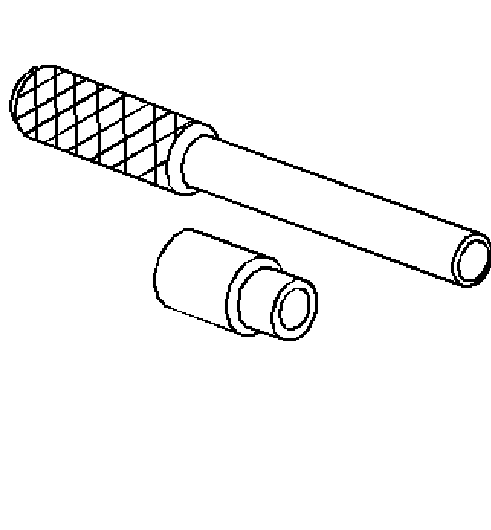
J 5239 Connecting Rod Bolt Guide Set
- Remove the oil pan. Refer to Oil Pan Replacement .
- Remove the oil pump. Refer to Oil Pump Replacement .
- Remove the crankshaft oil deflector. Refer to Crankshaft Oil Deflector Replacement .
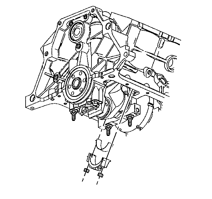
- Rotate the crankshaft until the piston and rod assembly to be serviced is at Bottom Dead Center (BDC).
- Remove the connecting rod nuts.
- Remove the connecting rod cap.
- Remove the lower connecting rod bearing.
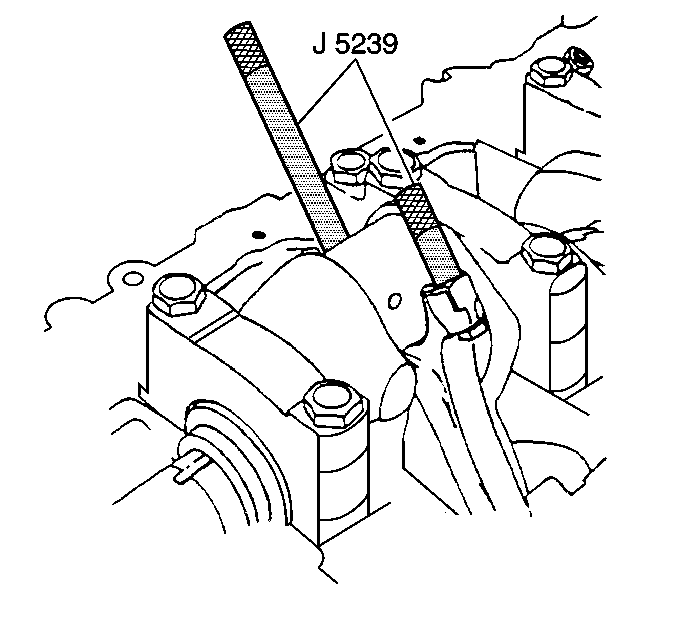
- Install the J 5239 .
- Push the piston and connecting rod up the cylinder in order to gain access to the upper connecting rod bearing.
- Remove the upper connecting rod bearing.
- Wipe oil from the connecting rod bearings and crankshaft connecting rod journal.
- Inspect the connecting rod bearings. Refer to Piston, Connecting Rod, and Bearing Cleaning and Inspection .
- Inspect the connecting rod cap and connecting rod. Refer to Piston, Connecting Rod, and Bearing Cleaning and Inspection .
- Inspect the crankshaft connecting rod journal. Refer to Crankshaft and Bearing Cleaning and Inspection .
Important: Make identification marks on the connecting rods and the corresponding connecting rod caps.
Notice: Install thread protector in order to avoid damage to the crankshaft journal.
Installation Procedure
Tools Required
| • | J 5239 Connecting Rod Bolt Guide Set |
| • | J 36660-A Torque Angle Meter |
- Install upper connecting rod bearing into the connecting rod.
- Coat the inside surfaces of the upper connecting rod bearing with new engine oil.
- Use the J 5239 in order to pull the piston and rod assembly down to the crankshaft.
- Remove the J 5239 .
- Install the lower connecting rod bearing into the connecting rod cap.
- Coat the inside surfaces of the lower connecting rod bearing with new engine oil.
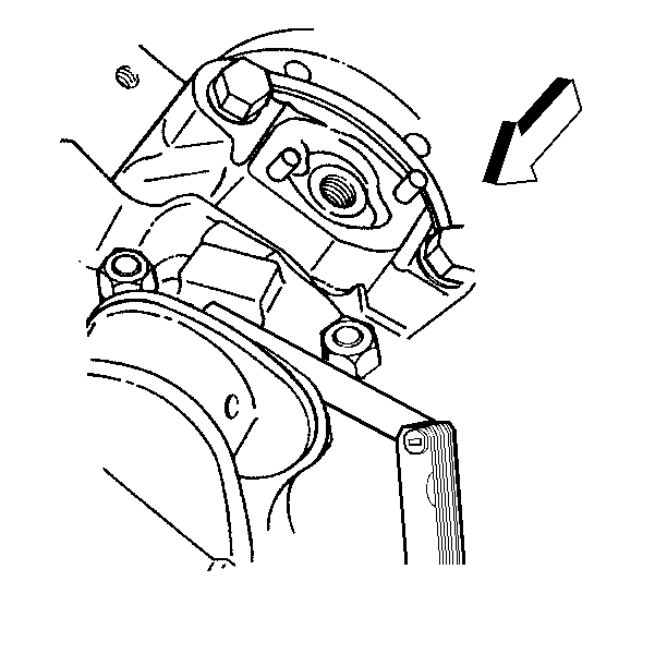
- Install the connecting rod cap with lower connecting rod bearing.
- Install the connecting rod nuts.
- Measure the connecting rod clearance using the following procedure:
- Install the crankshaft oil deflector. Refer to Crankshaft Oil Deflector Replacement .
- Install the oil pump. Refer to Oil Pump Installation .
- Install the oil pan. Refer to Oil Pan Replacement .
Notice: Use the correct fastener in the correct location. Replacement fasteners must be the correct part number for that application. Fasteners requiring replacement or fasteners requiring the use of thread locking compound or sealant are identified in the service procedure. Do not use paints, lubricants, or corrosion inhibitors on fasteners or fastener joint surfaces unless specified. These coatings affect fastener torque and joint clamping force and may damage the fastener. Use the correct tightening sequence and specifications when installing fasteners in order to avoid damage to parts and systems.
Tighten
Tighten the connecting rod nuts to 20 N·m
(15 lb ft). Evenly turn the nuts an additional 75 degrees using
the J 36660-A
.
| 9.1. | Install all connecting rod bearings. |
| 9.2. | Lightly tap each connecting rod parallel to the crankpin in order to make sure the connecting rods have clearance. |
| 9.3. | Measure the side clearance between the connecting rod caps using a feeler gage, or dial indicator. Refer to Crankpin (Rod Side Clearance) in Engine Mechanical Specifications for the connecting rod side clearance. |
