Engine Oil Leak at Crankshaft Rear Main Oil Seal (Install Revised Crankshaft Rear Main Oil Seal Using Revised Rear Main Seal Installer and Remover Tools)

| Subject: | Engine Oil Leak at Crankshaft Rear Main Oil Seal (Install Revised Crankshaft Rear Main Oil Seal Using Revised Rear Main Seal Installer and Remover Tools) |
| Models: | 1986-2008 GM Passenger Cars and Light Duty Trucks (including Saturn) |
| with 2.8L, 3.1L, 3.4L, 3.5L, 3.9L 60 Degree V6 Engine (VINs D, E, F, J, K, L, M, N, R, S, T, V, W, X, Z, 1, 8, 9, W, R -- RPOs LG6, LA1, LNJ, LG8, LL1 or LX9, L82, LL2, LB8, LHO, LG5, LB6, LE2 or LQ1, LH7, LC1, LX9, L44, LZ4, LZE, LZ9, LGD, LZ8, LZG) |
This bulletin is being revised to add the 2008 model year and new rear main seal remover tool and removal procedure. Please discard Corporate Bulletin Number 05-06-01-019D (Section 06 -- Engine/Propulsion System).
Notice: This bulletin only applies to 60 degree V6 engines . Some of the discontinued 60 degree V6 engine VINs and RPOs may have carried over to other new model year engines and may no longer be a 60 degree V6 engine. So this bulletin may not apply. It is very important to verify that the following information is correct before using this bulletin:
| • | Year of vehicle (e.g. N = 1992) |
| • | V6 Engine Liter size (e.g. 3.4L) |
| • | VIN CODE (e.g. X) |
| • | RPO (e.g. LQ1) |
If ALL the information from the vehicle (year, size, VIN Code, RPO) you're working on can be found under the models listed above, then this bulletin applies to that engine. If one or more of the vehicle's information can NOT be found under the models listed above, then this bulletin does NOT apply.
Important: This bulletin does not apply to 2004-2007 Saturn VUE models with 3.5L DOHC V6 Engine (VIN 4 - RPO L66) or 2005-2008 Cadillac CTS with 2.8L HFV6 Engine (VIN T - RPO LP1).
Condition
Some customers may comment on external oil leakage.
Correction
Important: Before replacement of the new design crankshaft rear main oil seal, be sure the PCV system is operating correctly.
Notice: The new seal described below comes with a protective nylon sleeve already installed in the seal. This sleeve assures that the seal is installed in the correct direction and also protects the seal from getting damaged during installation. Do not remove the protective sleeve from the seal; if removed, the installation tool (EN-48108) will not work.
A new design crankshaft rear main oil seal and installation tool (EN-48108) has been released. This seal incorporates features that improve high mileage durability. Replace the crankshaft rear main oil seal with the new design rear main oil seal, P/N 12592195, using the following service procedures.
Tools Required
Important: TOOLS WERE SHIPPED TO YOUR DEALERSHIPS. IF YOU HAVE NOT RECEIVED THEM OR THEY ARE LOST, PLEASE CALL GM SPECIAL SERVICE TOOLS AT 1-800-GM-TOOLS.
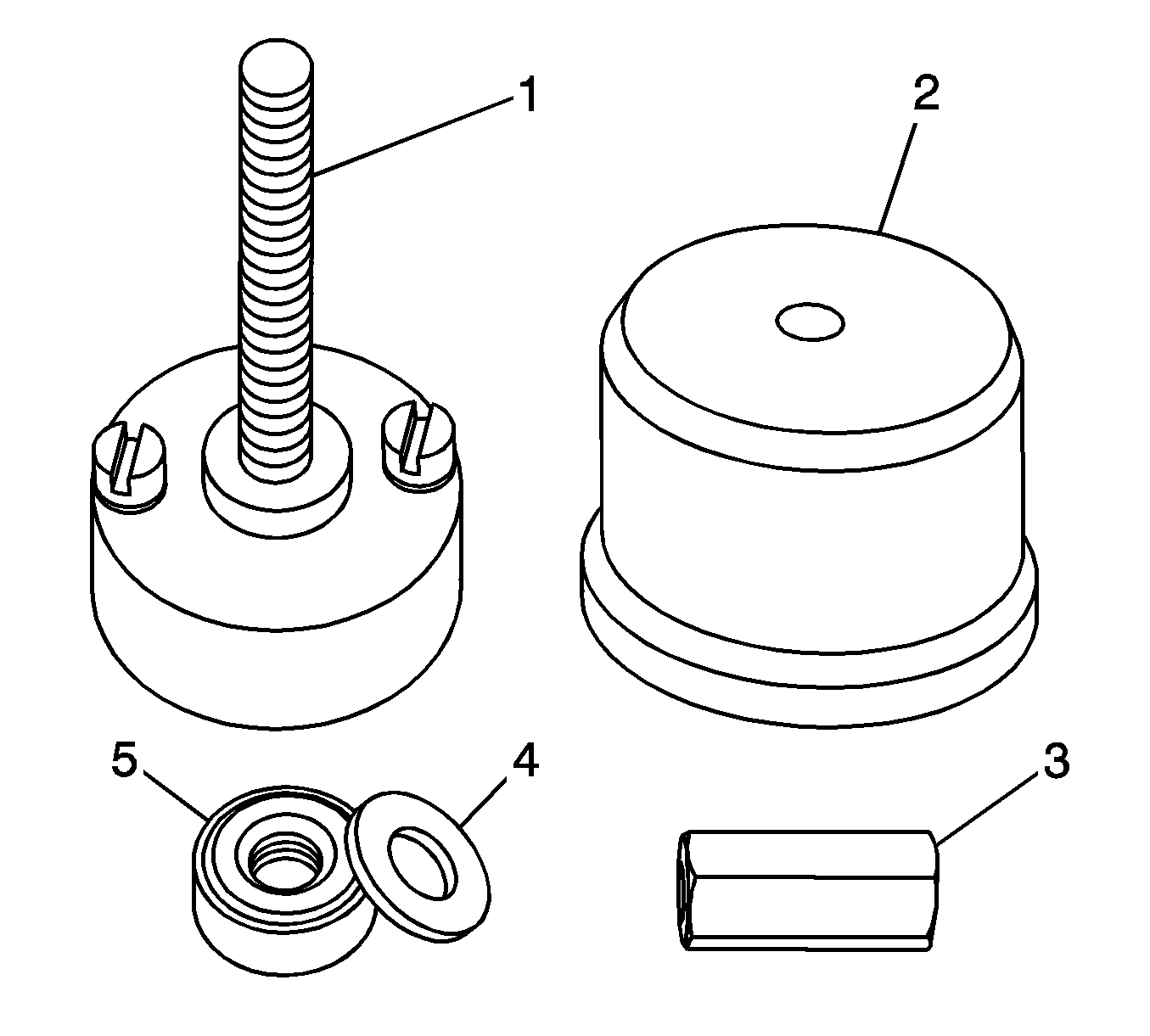
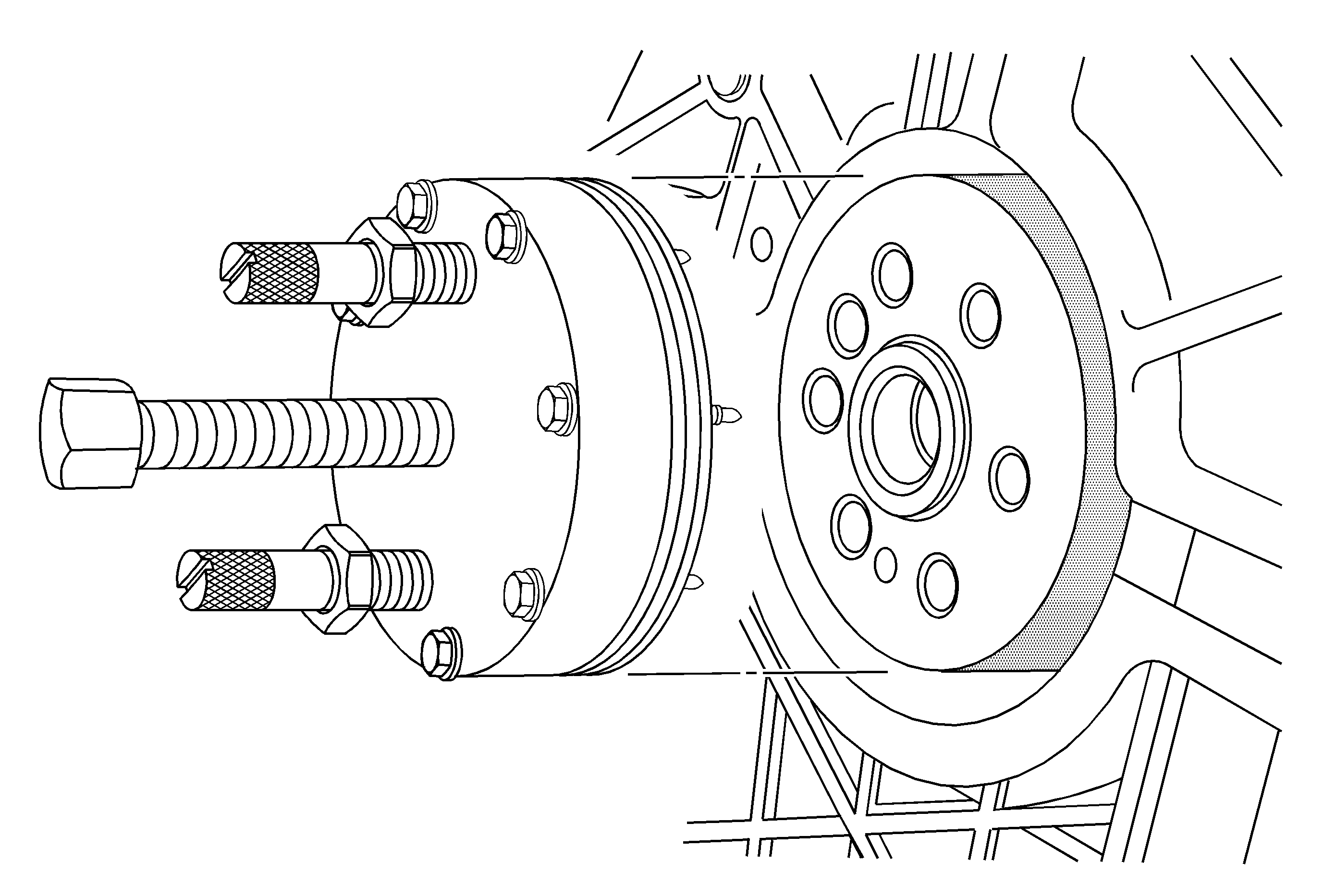
EN-48108 Rear Main Oil Seal Installation Tool
This tool has a unique design to allow the technician to easily install the rear main seal squarely to the correct depth and direction. Before proceeding with installation, review the above illustration to become familiar with the following components:
- Mandrel
- Drive Drum
- Drive Nut
- Washer
- Bearing
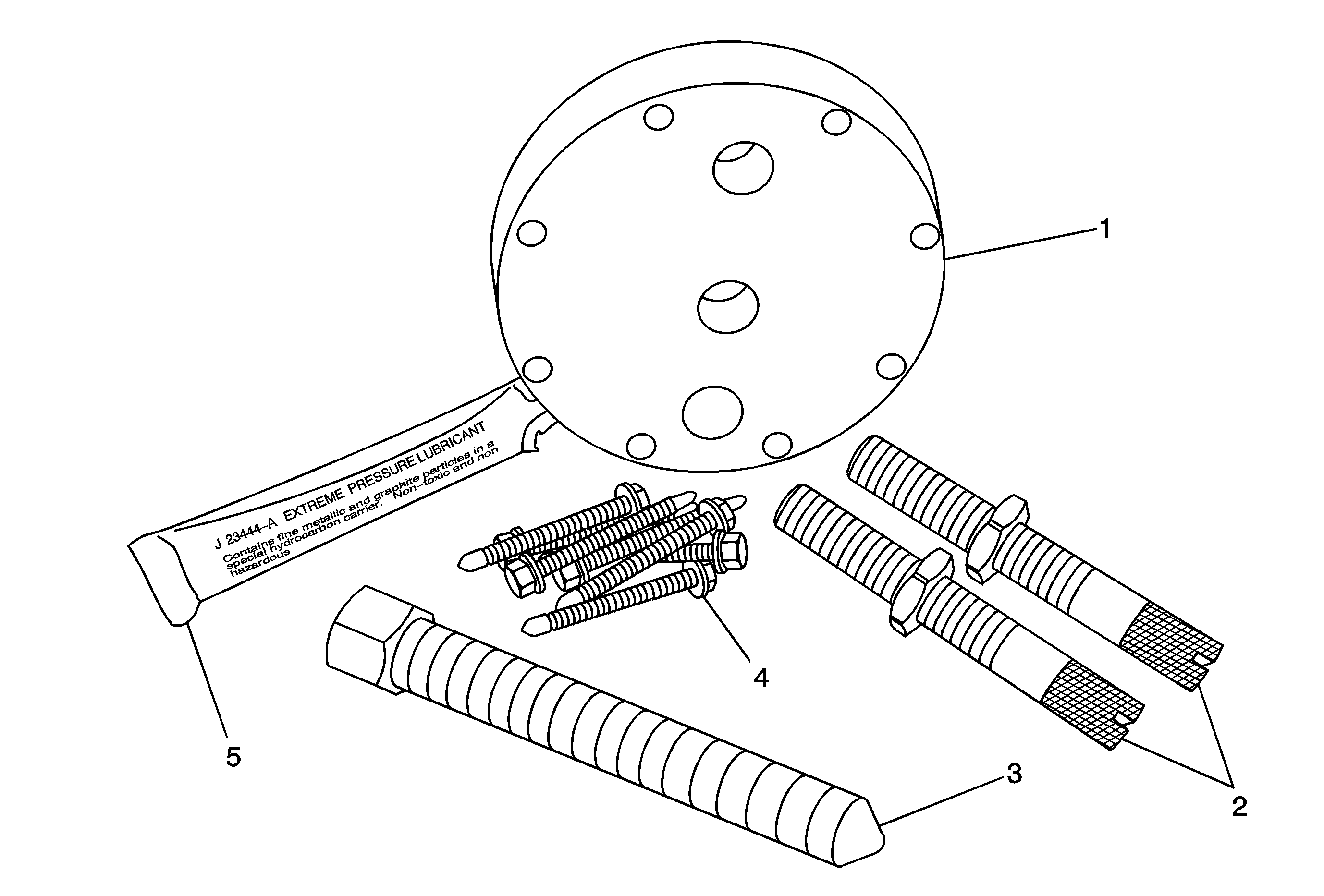
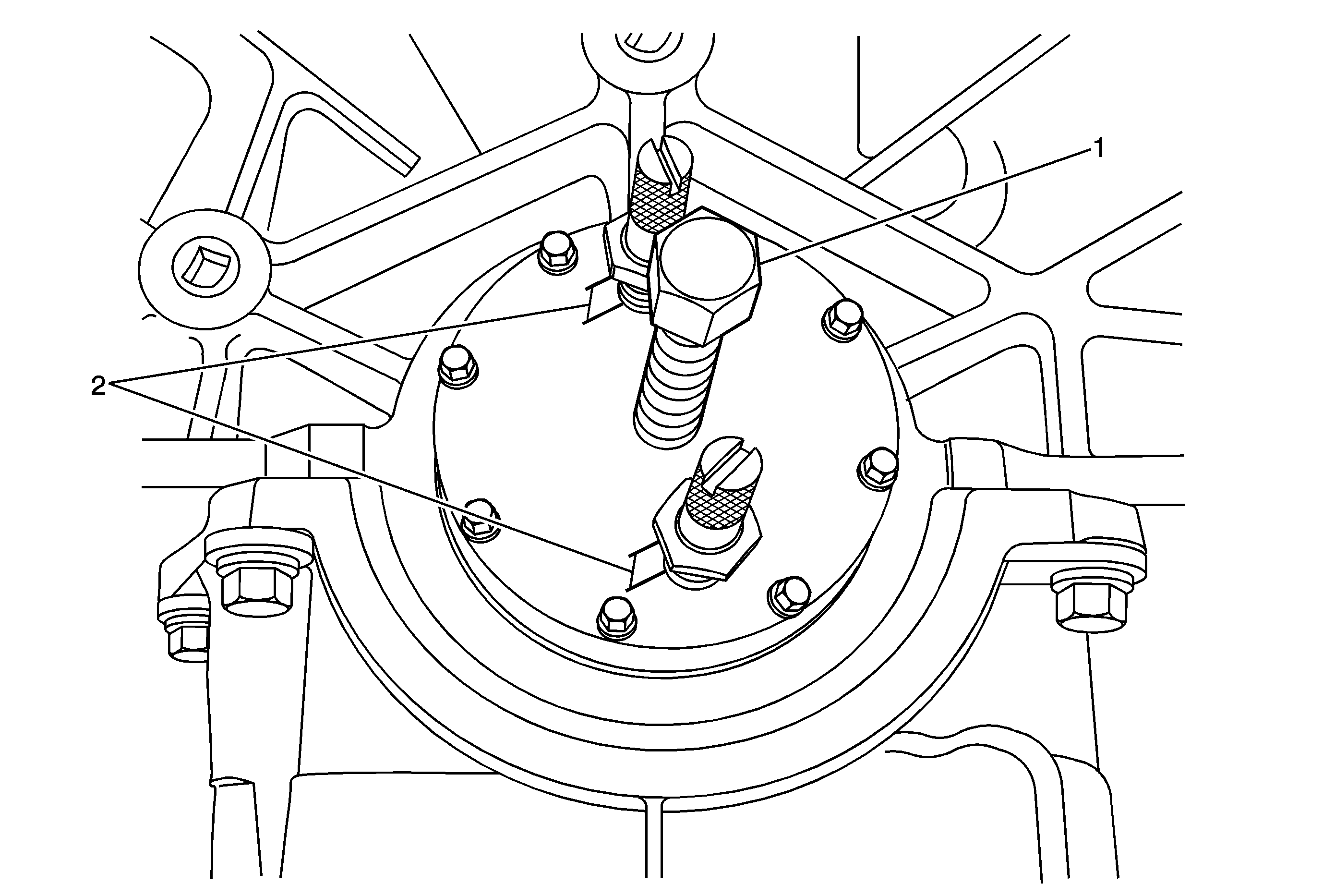
EN-48672 Rear Main Oil Seal Remover Tool
This tool has a unique design to allow the technician to easily remove the rear main seal without nicking the crankshaft sealing surface when removing the seal. Before proceeding with removal, review the above illustration to become familiar with the following components:
- Removal Plate
- Threaded Adjustment Pins and Jam Nuts
- Force Screw
- #2 Self Drill Screws 38 mm (1.5 in) long 8 needed
- Extreme Pressure Lubricant
Removal Procedure
- Remove the transmission. Refer to Transmission Replacement in SI or the appropriate Service Manual.
- Remove the engine flywheel. Refer to Engine Flywheel Replacement in SI or the appropriate Service Manual.
- Install the removal plate (2) and both threaded adjustment pins and jam nuts (1) into the back of the crankshaft flange and secure the plate with adjustment pins and jam nuts.
- Install #2 Self Drill Screws 38 mm (1.5 in) long, eight needed, (1) and tighten down flush to the plate.
- Install the force screw (1) and back off both jam nuts (2) and continue to turn the force screw (1) into the removal plate to remove the seal from the crankshaft.
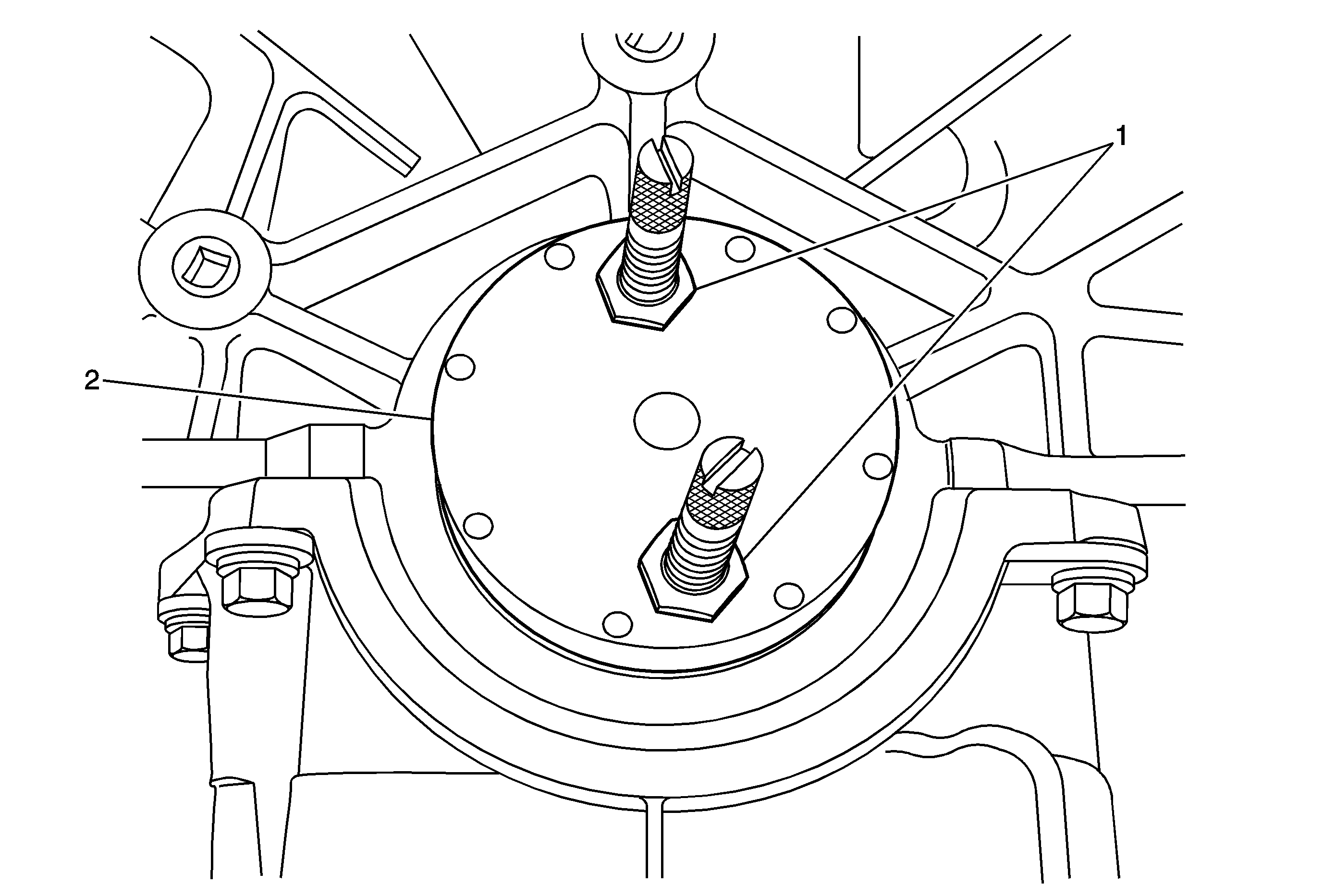
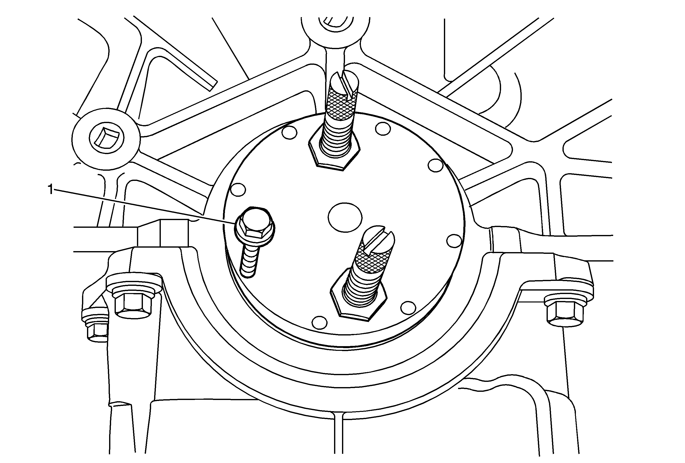
Important: Before installing the force screw, apply a small amount of the Extreme Pressure Lubricant J 23444-A, provided in the tool kit.
Once the seal is removed from the crankshaft, remove and save all eight screws and discard the old seal.
Notice: Clean the crankshaft sealing surface with a clean, lint free towel. Inspect the lead-in edge of the crankshaft for burrs or sharp edges that could damage the rear main oil seal. Remove any burrs or sharp edges with crocus cloth or equivalent before proceeding.
Installation Procedure
Notice: Do not remove the protective nylon sleeve from the new rear main seal prior to installation. The EN-48108 is designed to install the rear main seal with the protective sleeve in place. Never apply or use any oil, lubricants or sealing compounds on the crankshaft rear main oil seal.
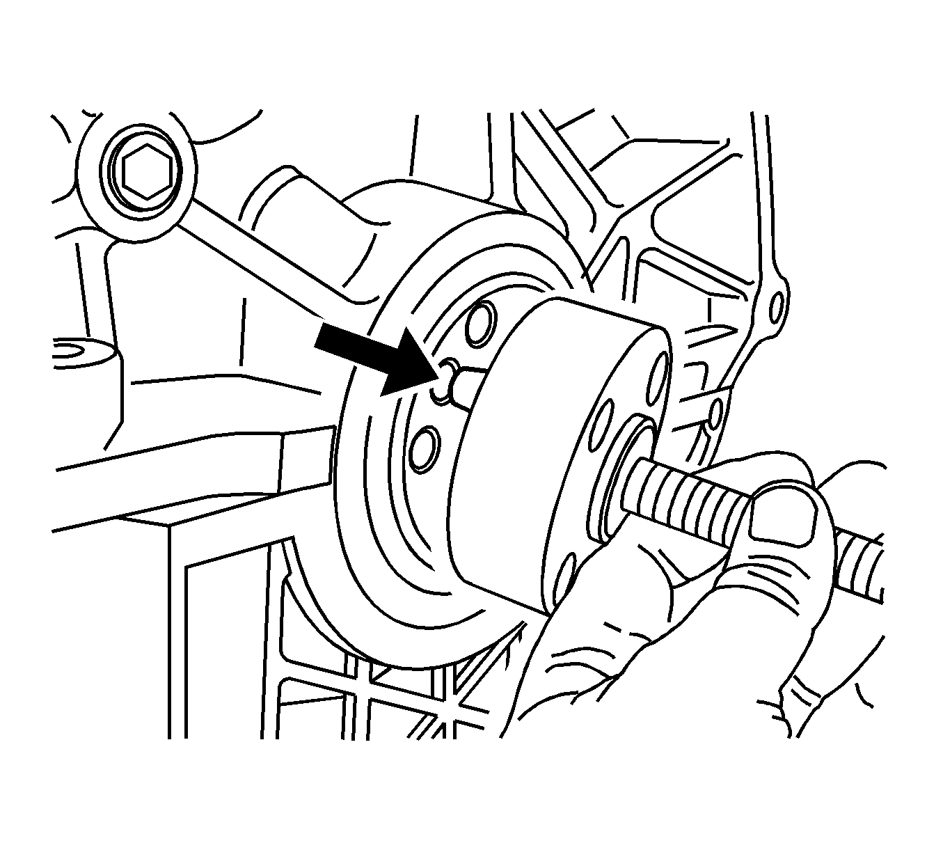
- Align the mandrel dowel pin (EN-48108) to the dowel pin hole in the crankshaft. Refer to the above illustration.
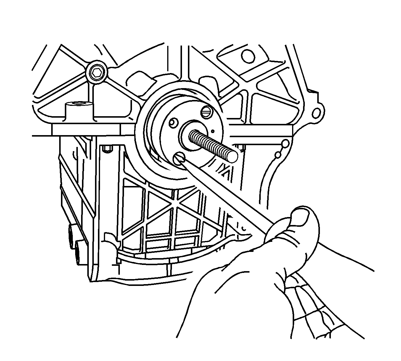
- Using a large flat-bladed screwdriver, tighten the two mandrel screws to the crankshaft. Ensure that the mandrel is snug to the crankshaft hub. Refer to the above illustration.
- Install the rear main seal (1), with the protective nylon sleeve attached (2), onto the mandrel. The seal, if properly installed, will center on a step that protrudes from the center of the mandrel. As an error proof, seal will fit only one way onto the mandrel. Refer to the above illustration.
- Install the outer drive drum onto the mandrel (EN-48108). Install the bearing, washer and the drive nut onto the threaded shaft. Refer to the above illustration.
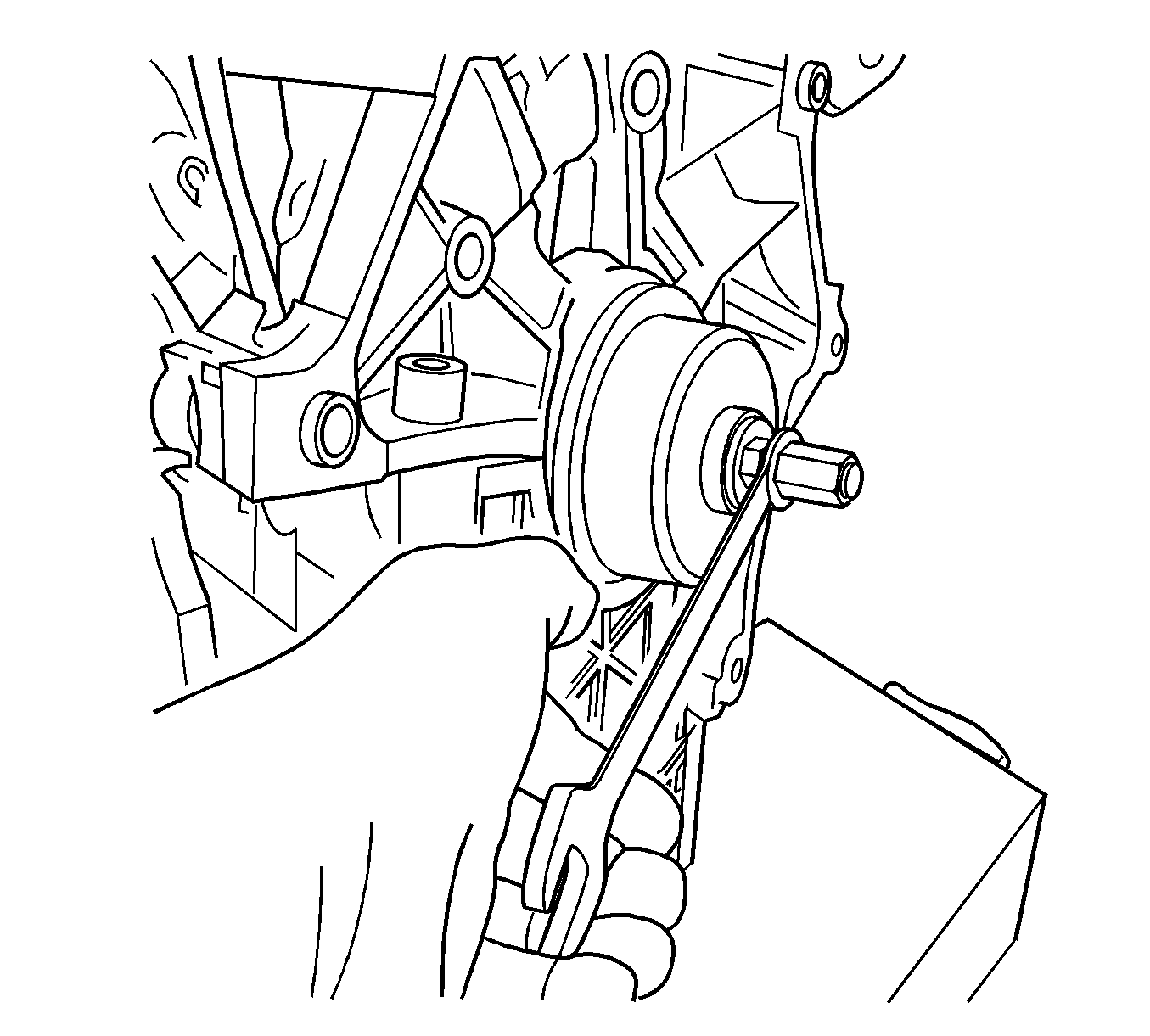
- Using a wrench, turn the drive nut on the mandrel (EN-48108), which will push the seal into the engine block bore. Turn the wrench until the drive drum is snug and flush against the engine block. Refer to the above illustration.
- Loosen and remove the drive nut, washer, bearing and drive drum. Discard the protective nylon sleeve.
- Verify that the seal has seated properly.
- Use a flat-bladed screwdriver to remove the two attachment screws from the mandrel and remove the mandrel from the crankshaft hub. Refer to the above illustration.
- Install the engine flywheel. Refer to Engine Flywheel Replacement in SI or the appropriate Service Manual.
- Install the transmission. Refer to Transmission Replacement in SI or the appropriate Service Manual.
- Inspect for proper fluid levels.
- Inspect for leaks.
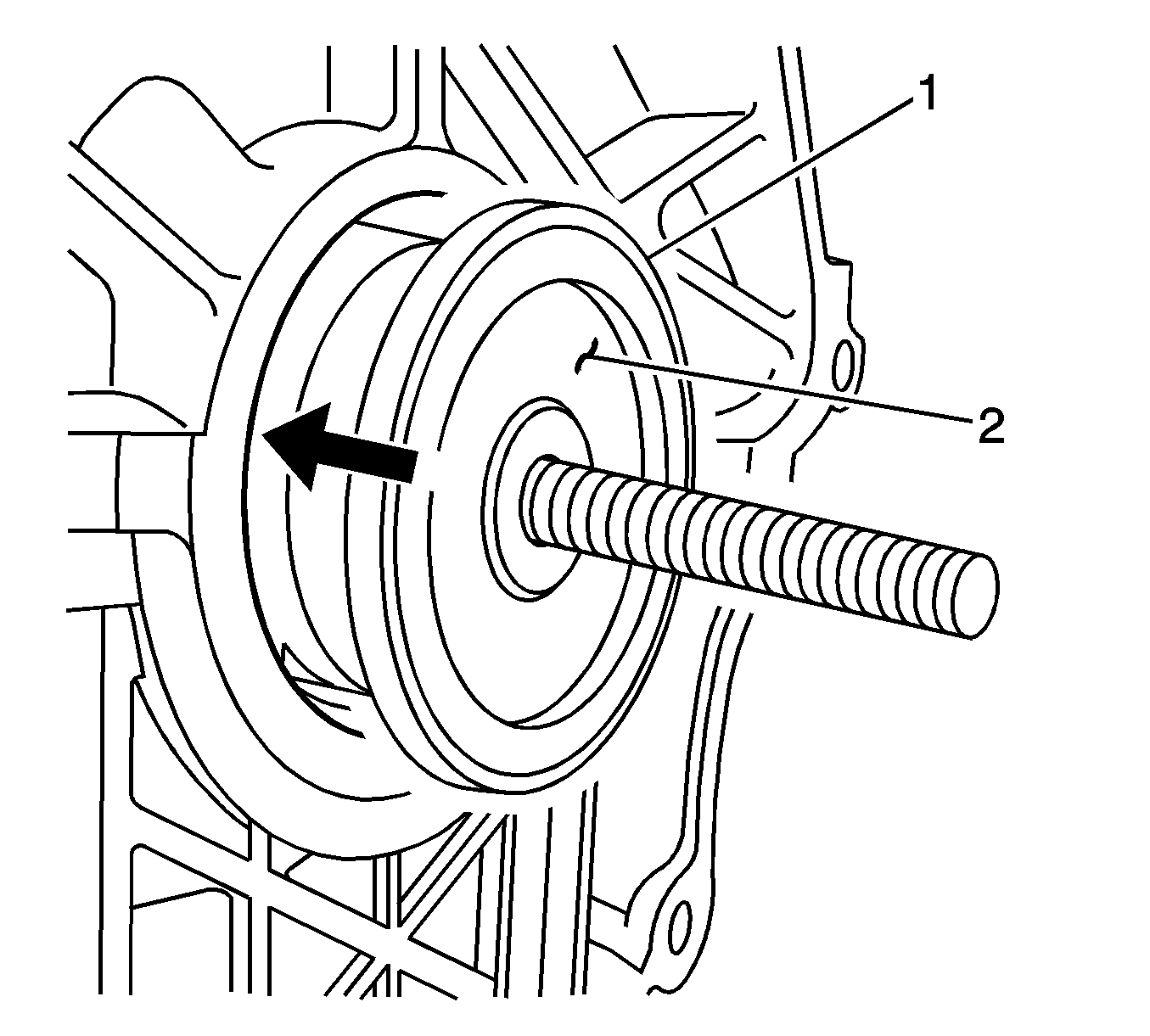
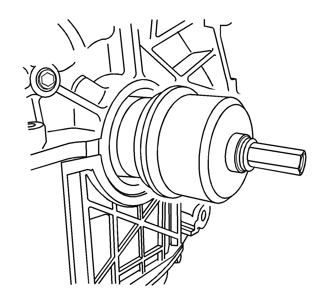
Important: Before installing the outer drive drum, bearing, washer and the drive nut onto the threaded shaft, apply a small amount of the Extreme Pressure Lubricant J 23444-A, provided in the tool kit.

Parts Information
Part Number | Description |
|---|---|
12592195 (U.S. and Canada) | Seal Assembly, Crankshaft Rear Main Oil (Includes Nylon Protective Sleeve) |
Warranty Information
For vehicles repaired under warranty, use:
Labor Operation | Description | Labor Time |
|---|---|---|
J1120 | Seal, Crankshaft Rear Main - Replace | Use Published Labor Operation Time |
