Tools Required
| • | J 24204-2 Bar and Stud Assembly |
| • | J 44530 Clutch Piston Spring Compressor |
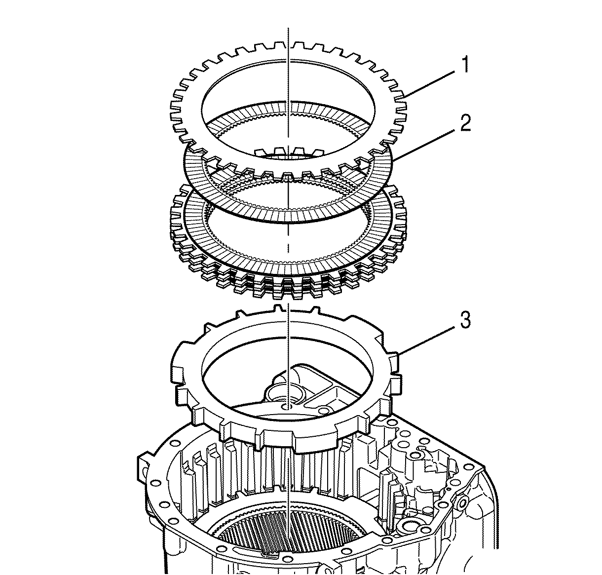
- Install the low and reverse clutch backing plate (3).
- Starting with a low and reverse clutch fiber plate, alternately install the remaining 5 low and reverse clutch fiber plates (2) and the low and reverse clutch steel plates (1).
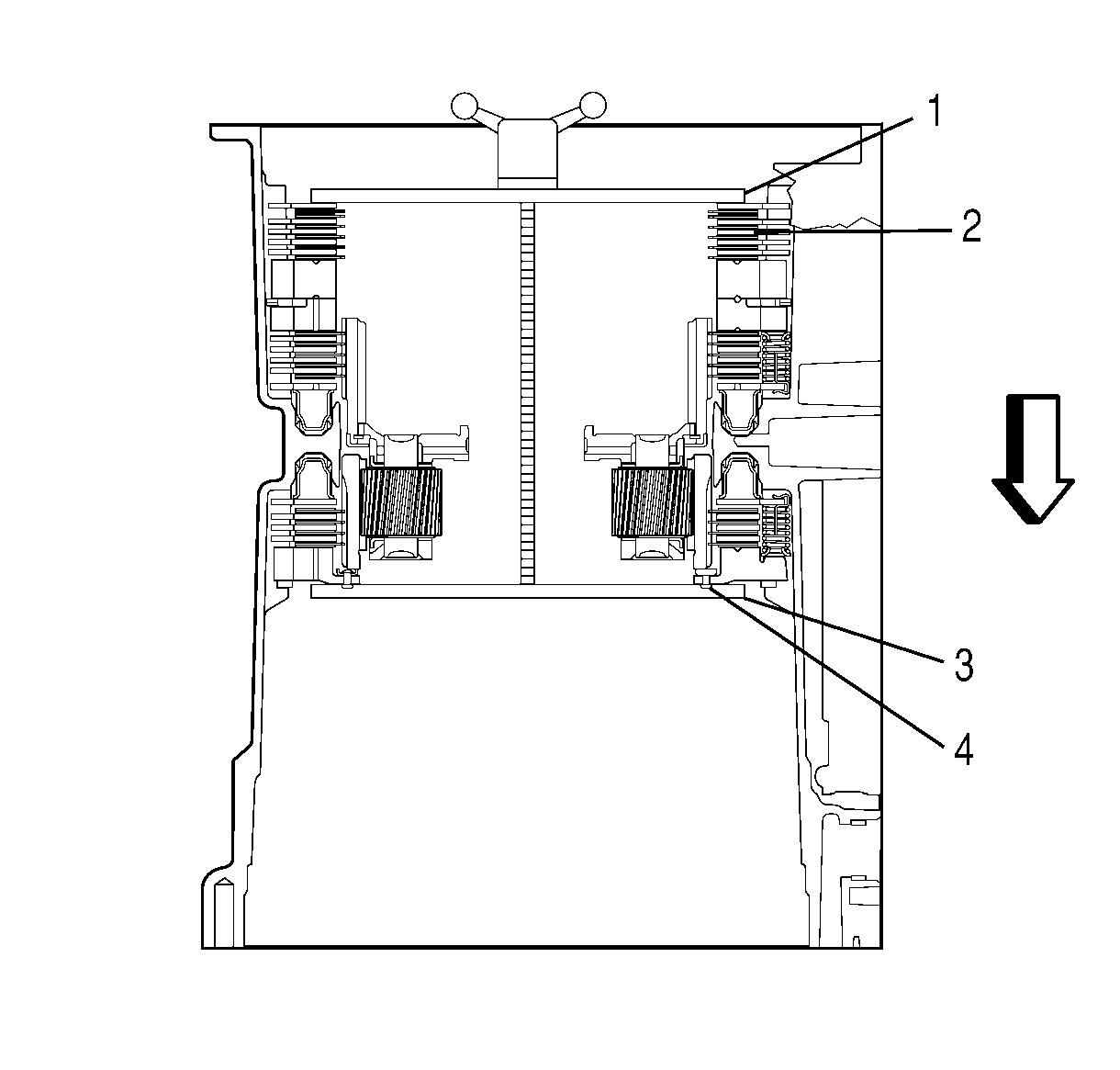
- Install J 24204-2 (3) and J 44530 (1) into the transmission case.
- Make sure J 24204-2 does not damage the gear thrust plate rivets (4) on the 3rd, 5th, and reverse clutch backing plate assembly.
- Using the J 24204-2 wing nut, compress the low and reverse clutch plates (2) until hand tight.
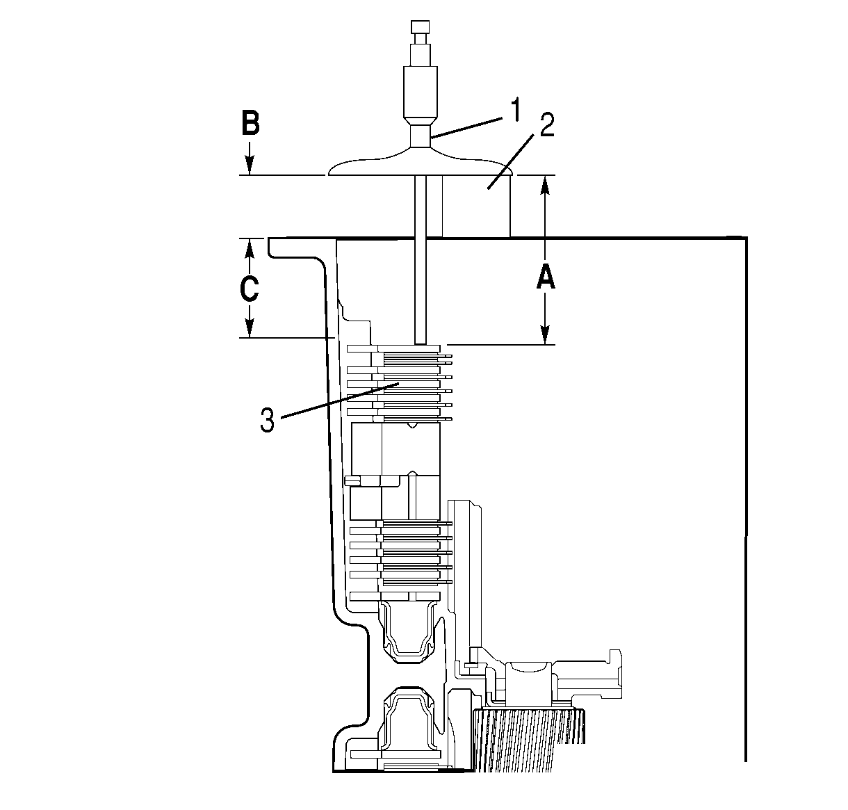
- Place a 25 mm (1 in) gage bar (2) on the rear surface of the transmission case at a location near J 44530 .
- Measure the distance from the top of the gage bar to the top of the low and reverse clutch stack (3) (Dimension A).
- Subtract dimension B, the width of the gage bar; from dimension A.
- Dimension C is the result of the subtraction.
- Select a low and reverse clutch steel plate based upon Dimension C. Refer to Selective Components Specifications .
- Remove J 24204-2 (3) and J 44530 (1).
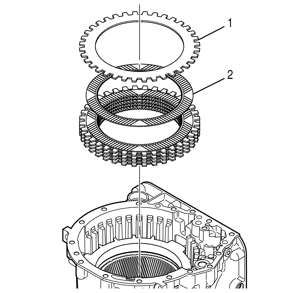
- Remove 6 low and reverse clutch fiber plates (2) and 5 low and reverse clutch steel plates (1).

Important: The low and reverse clutch backing plate installs in either direction. The plate may have no grooves, one side grooved, or both sides grooved.
Important: The low and reverse clutch pack uses a single selective steel plate. The low and reverse clutch pack is stacked out of order to allow determining the required selective steel plate part number. When properly stacked, the top plate is a steel plate and the next 2 plates are fiber plates. The selective steel plate is not stacked. Steel plates have an ID number stamped on a tang. The identification number that does not match the other identification numbers is the selective steel plate.
Notice: Refer to 3-5 Reverse Clutch Backing Plate Rivet Damage Notice in the Preface section.

Important: The low and reverse clutch plates need to be compressed enough to remove the coning from the plates. Hand tightening the wing nut of J 24204-2 should be sufficient to remove the coning.


Important: DO NOT damage the input carrier bushing when removing J 24204-2 from the transmission case. The threaded rod of J 24204-2 must pass through but not touch the bushing.

