Tyco/AMP Connectors CM 42-Way
Special Tools
J-38125 Terminal Repair Kit
Removal Procedure
- Locate the connector position assurance (CPA) on the connector body and pull the CPA out. The CPA is on the wire harness side of connector.
- Disconnect the connector from the component.
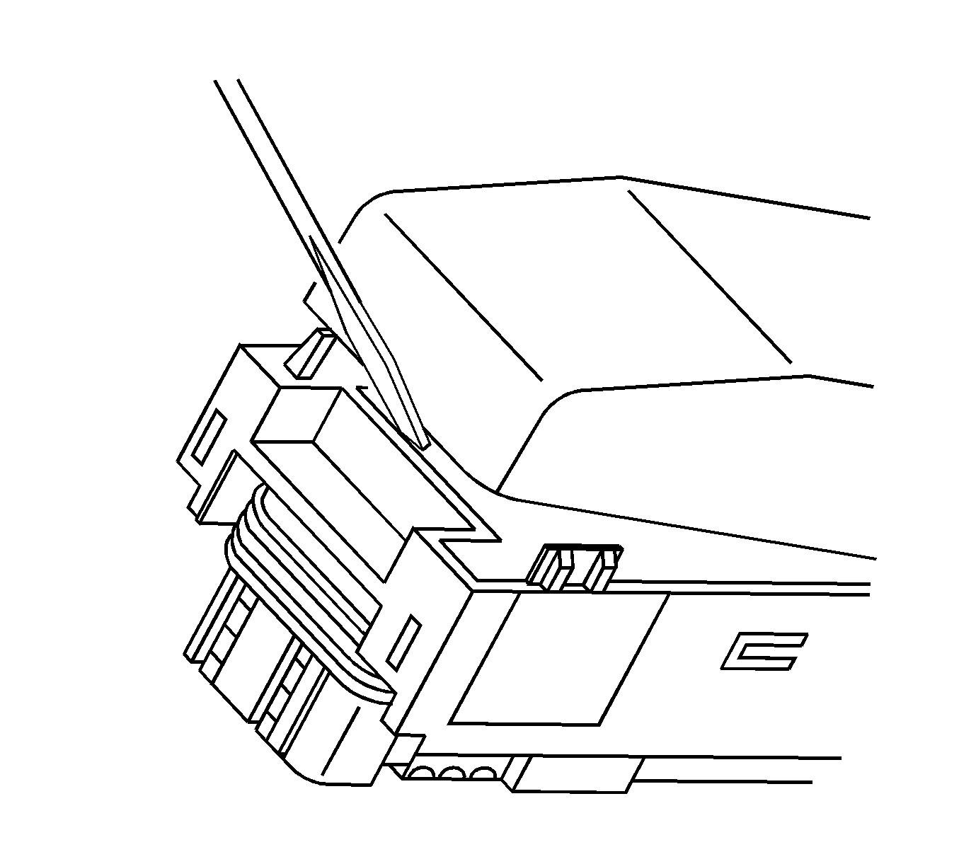
- Use a small flat-bladed tool to gently pry off the dress cover by inserting the tool under the cover opposite the harness side and prying up.
- Remove the cover.
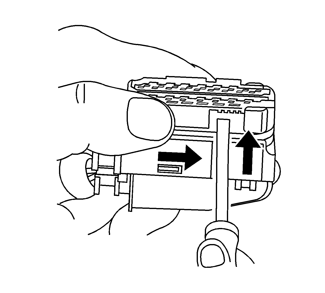
- Using a small flat-bladed tool, push on the side of the nose piece retainer while pushing the nose piece forward with your thumb. This will release the terminal position assurance (TPA).
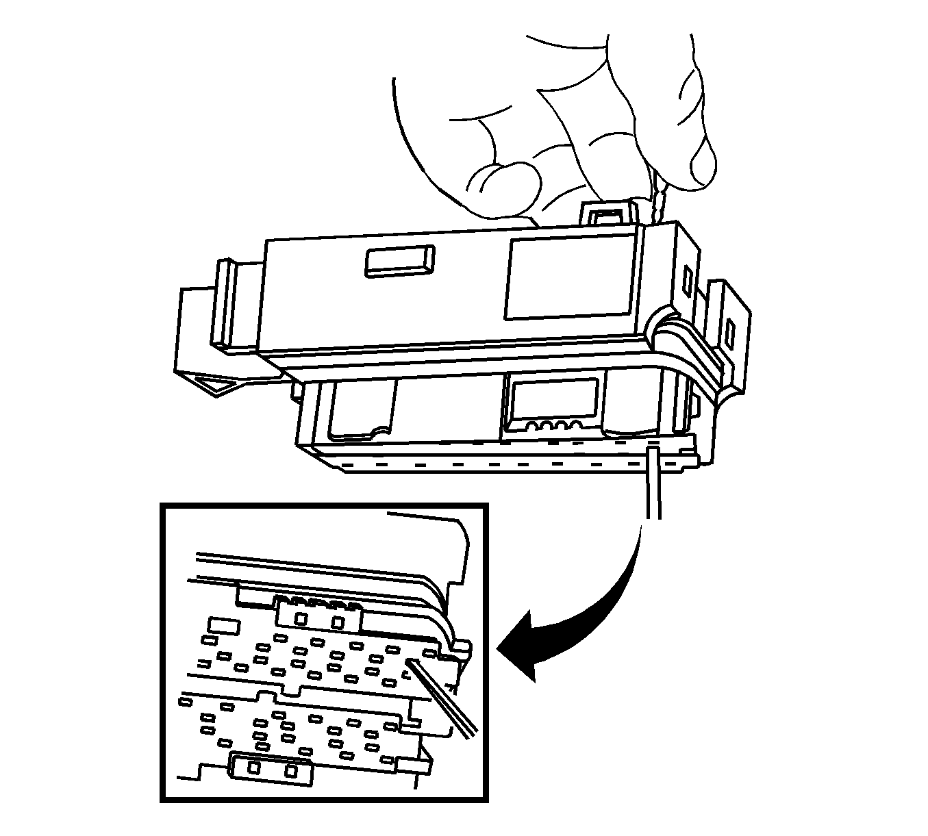
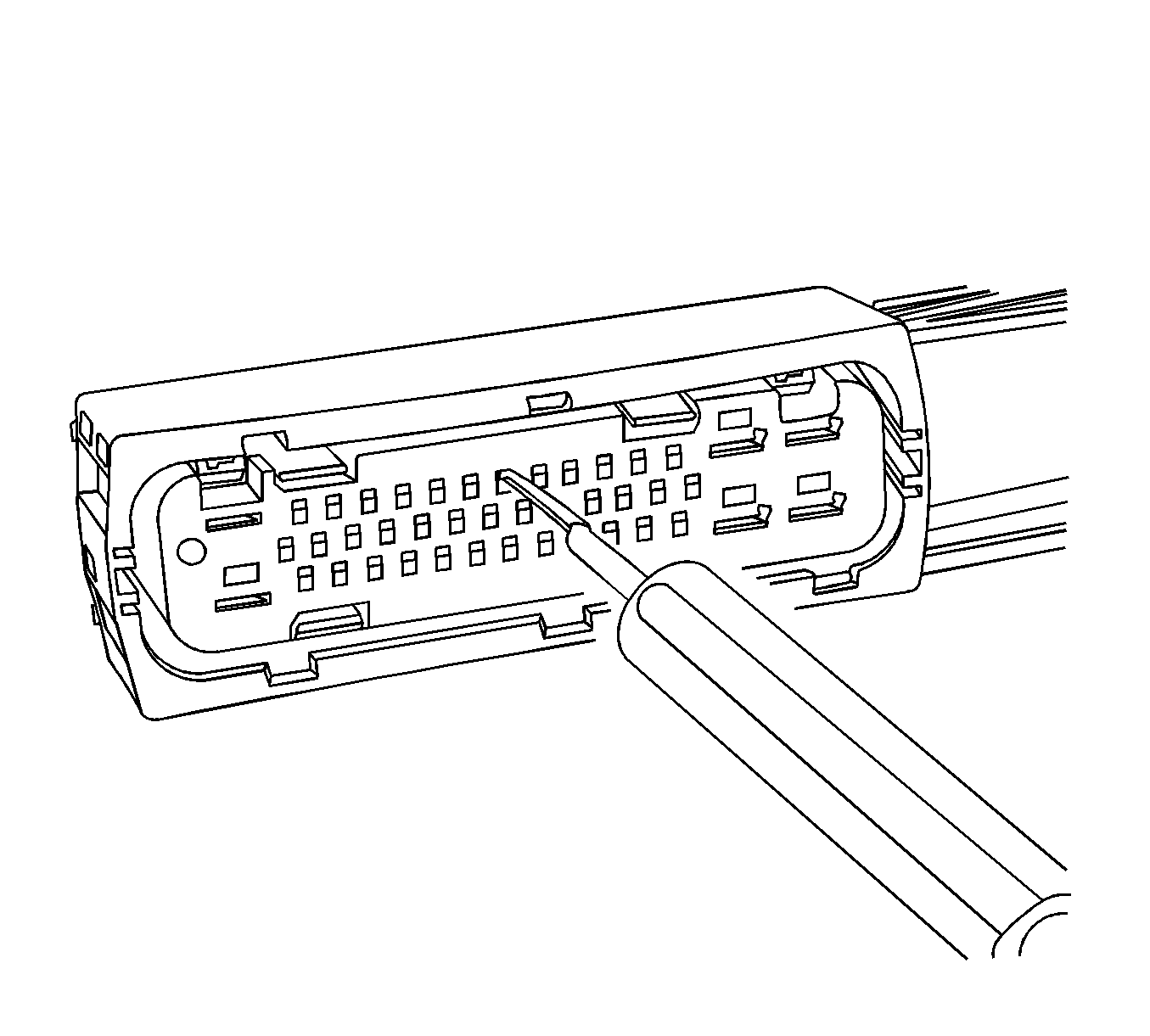
- Insert the J 38125-12A into the corresponding terminal release cavity. The release cavities are the 2 center rows of cavities on one half of the connector.
- Pressing the J 38125-12A tool in the release cavity of the terminal you are removing, gently pull the wire out of the back of the connector. Always remember never use force when pulling a terminal out of a connector. See the release tool cross reference in the Reference Guide of the J-38125 to ensure that the correct release tool is used.
Terminal Repair Procedure
Use the appropriate terminal and crimper in the J-38125 in order to replace the terminal.
Tyco/AMP Connectors 43-Way
Special Tools
J-38125 Terminal Repair Kit
Removal Procedure
Follow the steps below in order to remove terminals from the connector.
- Locate the lever lock on the wire dress cover. Slide the lever lock away from the connector body.
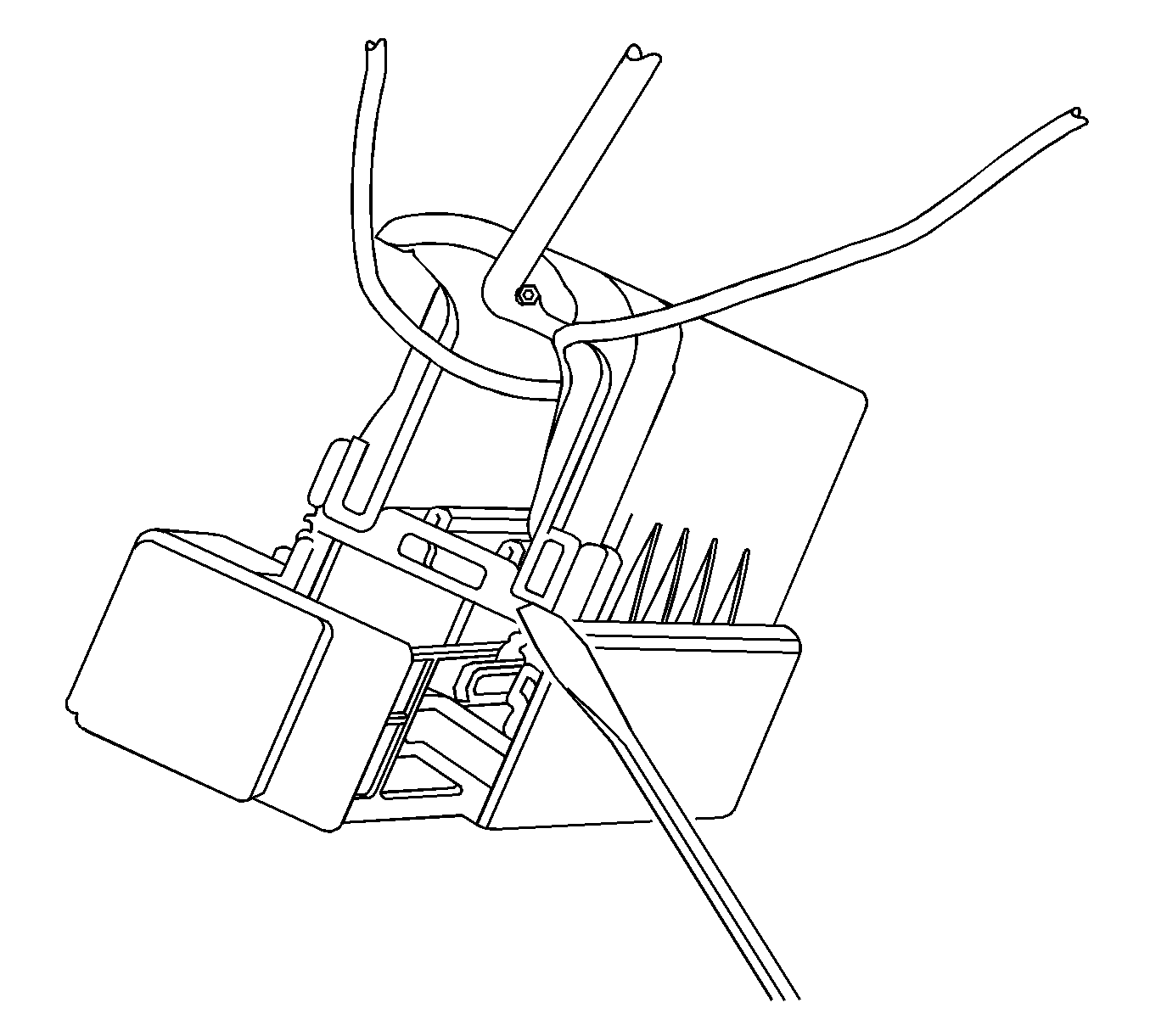
- Disconnect the connector from the component.
- Locate the dress cover locking tabs on the dress cover of the connector. Using a small flat-blade tool release all of the locking tabs.
- Once the locks are unlocked, lift the dress cover off.
- Release the TPA by inserting a small flat-blade tool into the blue locking tabs on both ends of the connector. Gently slide the TPA up to the released position on both ends.
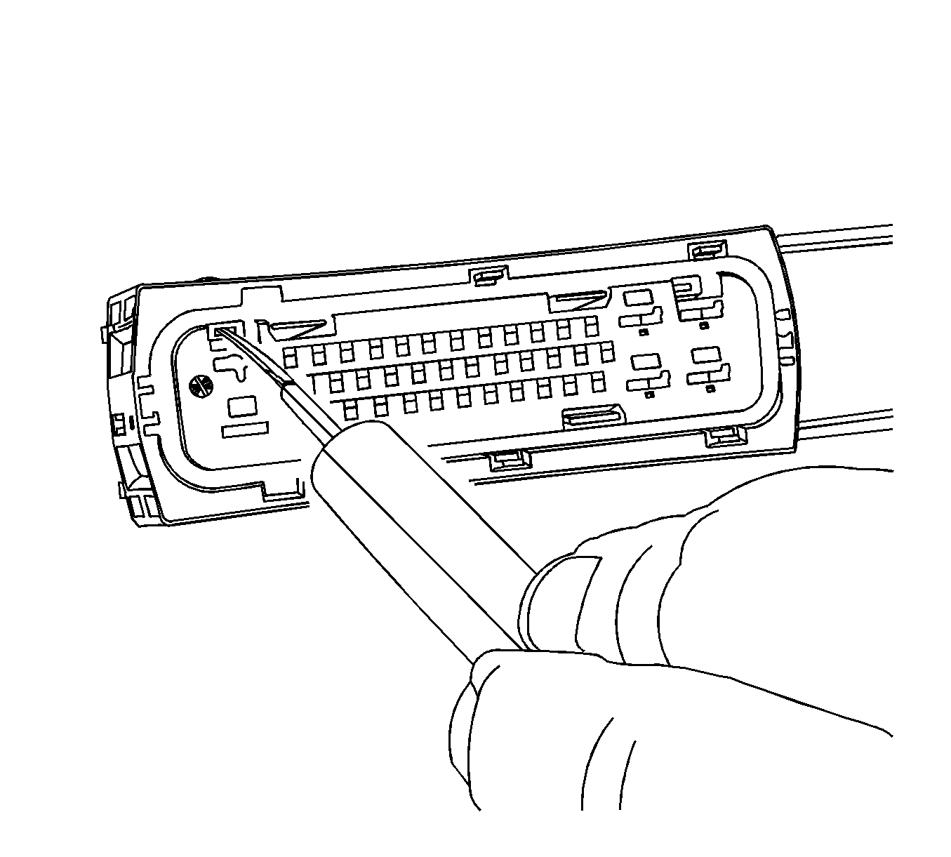
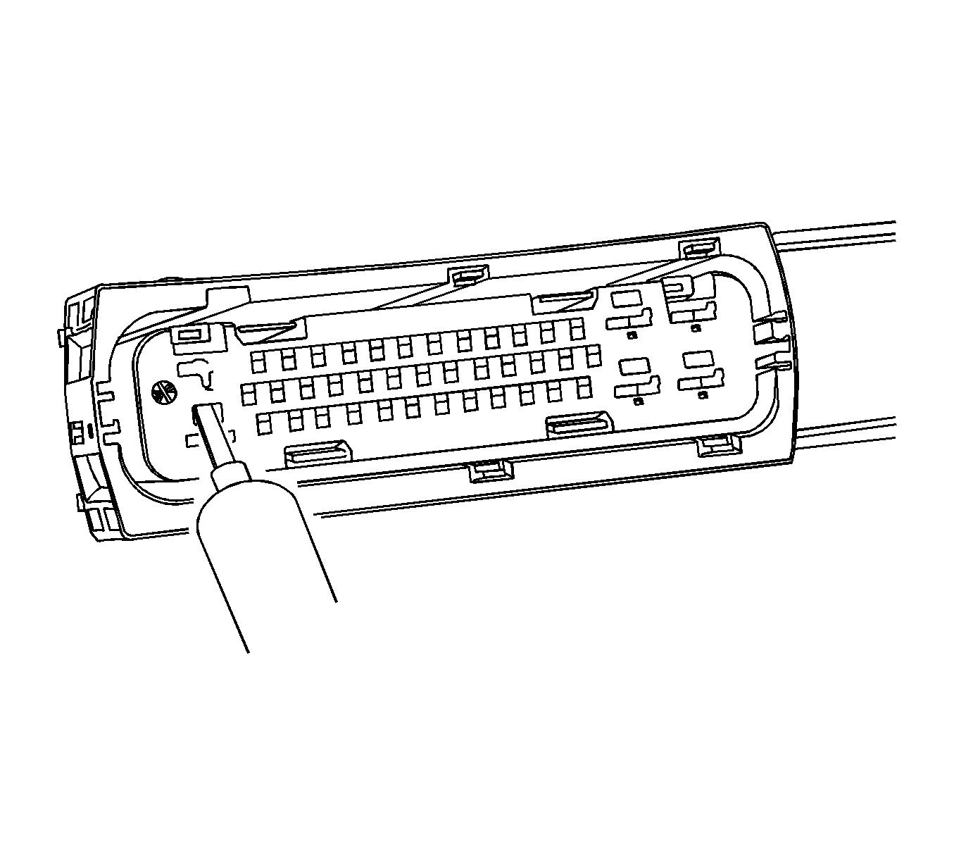
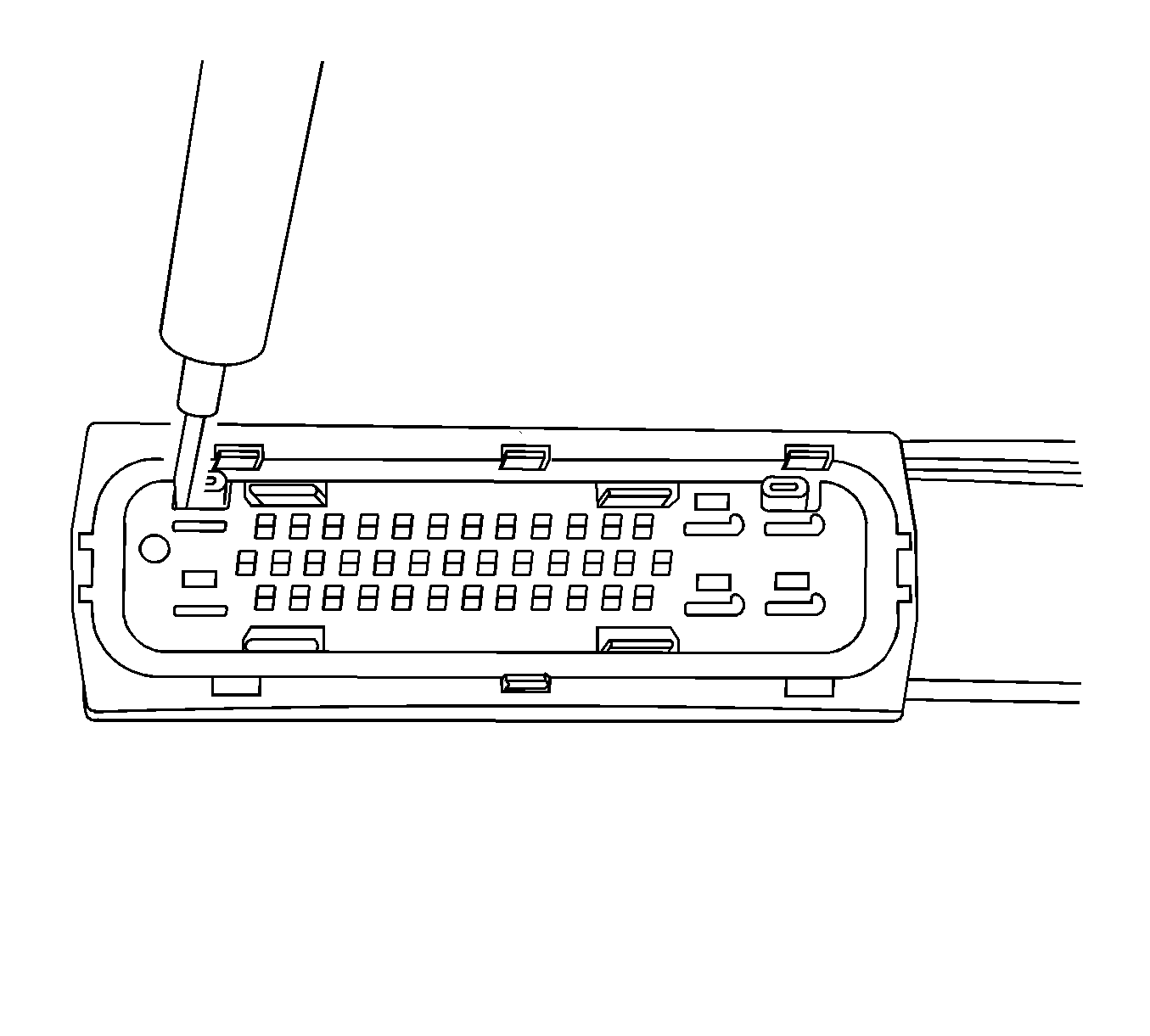
- For the larger terminals insert the J 38125-13A tool to release the terminals by inserting the tool into the terminal release cavity. For the smaller terminals insert the J 38125-12A tool to release the terminals by inserting the tool into the terminal release cavity. See the release tool cross reference in the Reference Guide of the J-38125 to ensure that the correct release tool is used.
- View of the release tool being used for the larger terminals.
- View of the release tool being used for the larger terminals.
- View of the release tool being used for the smaller terminals.
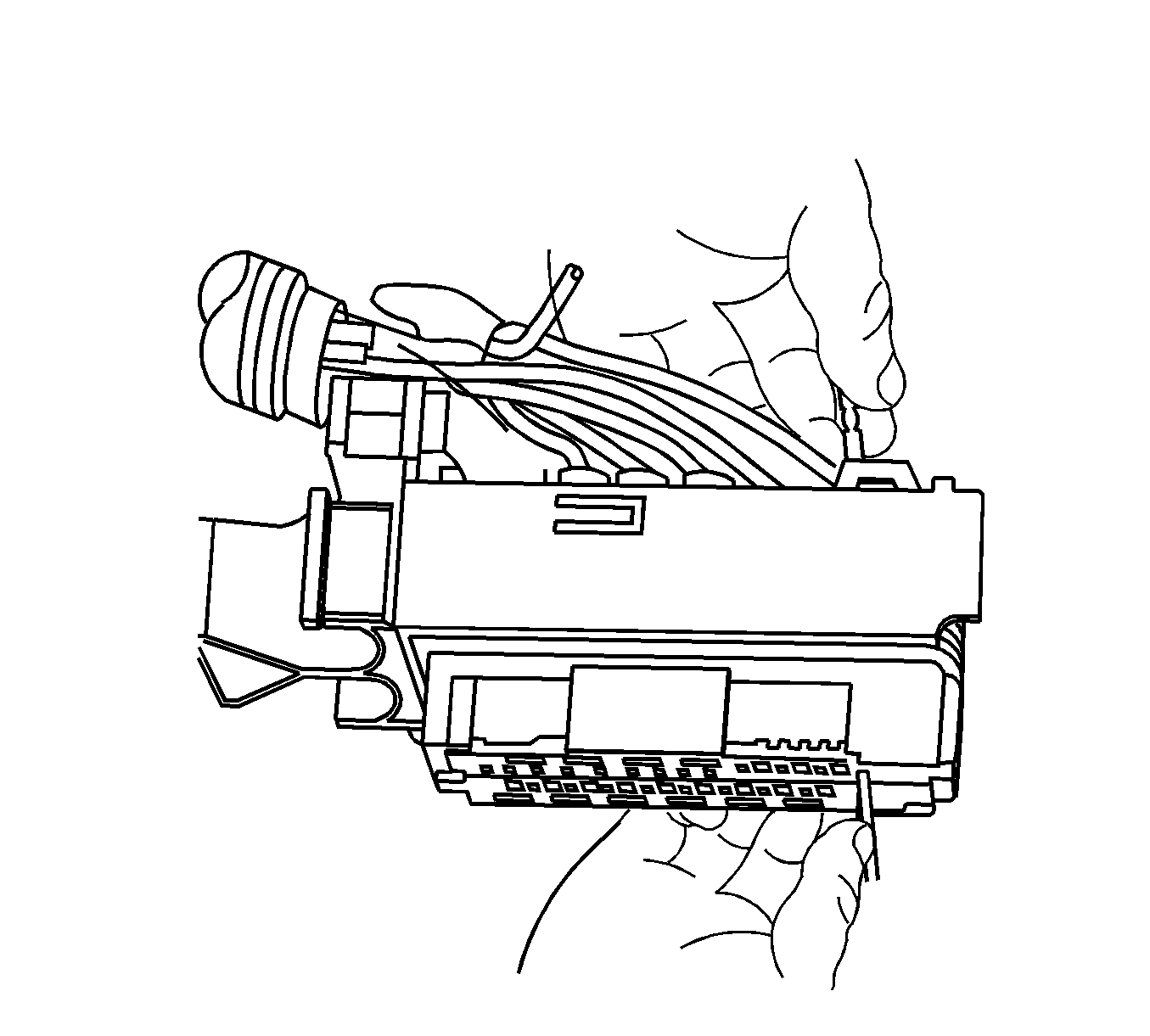
- While holding the removal tool in place, gently pull the wire out of the back of the connector. Always remember never use force when pulling a terminal out of a connector.
Note: Always use care when removing a terminal position assurance (TPA) in order to avoid damaging it.
Repair Procedure
Use the appropriate terminal and follow the instructions in the J-38125 .
Location of the terminal in the repair tray and the proper crimp tool can be found in the appropriate connector end view.
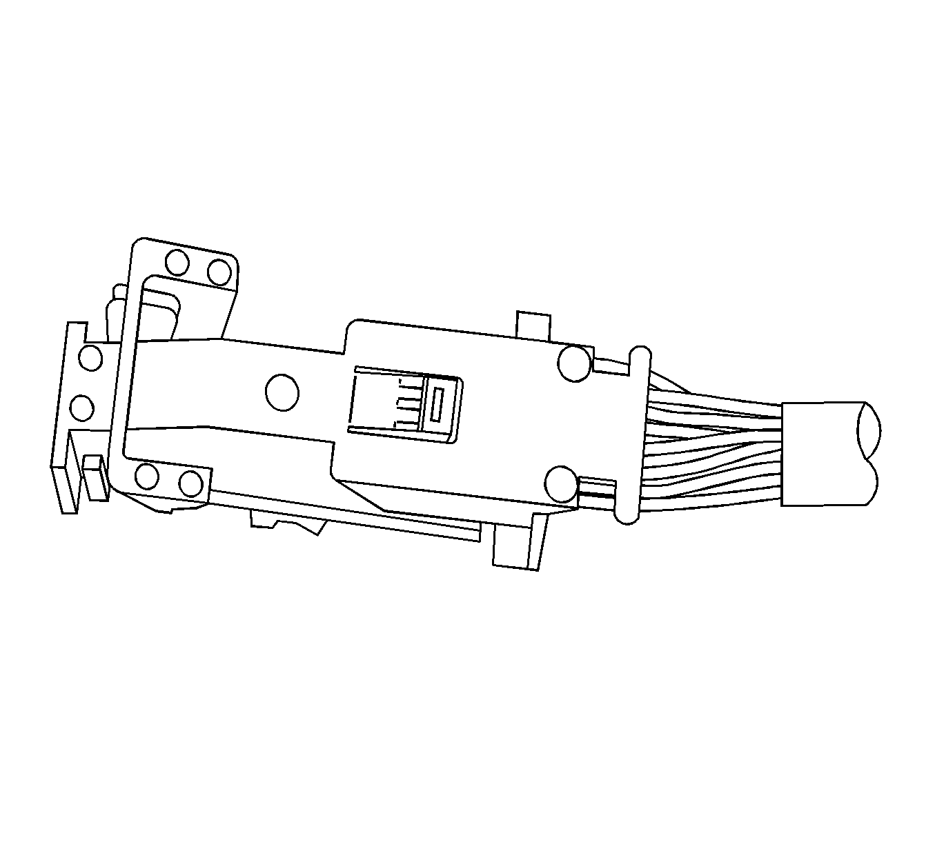
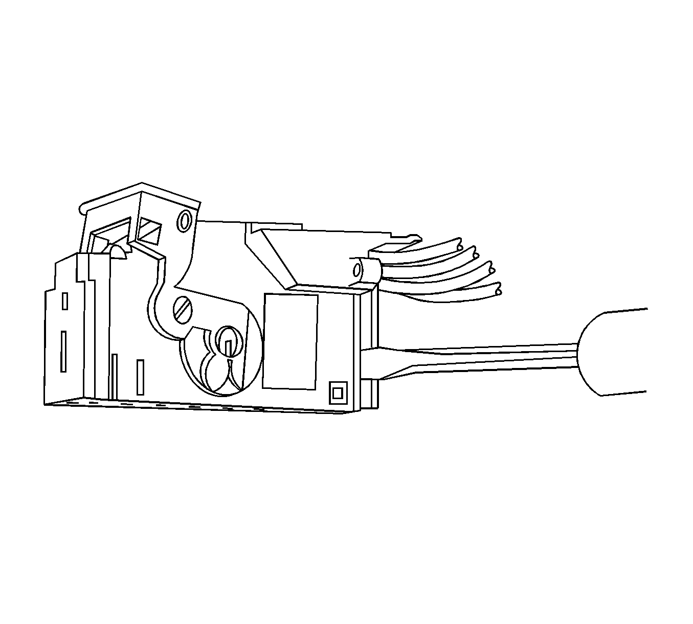
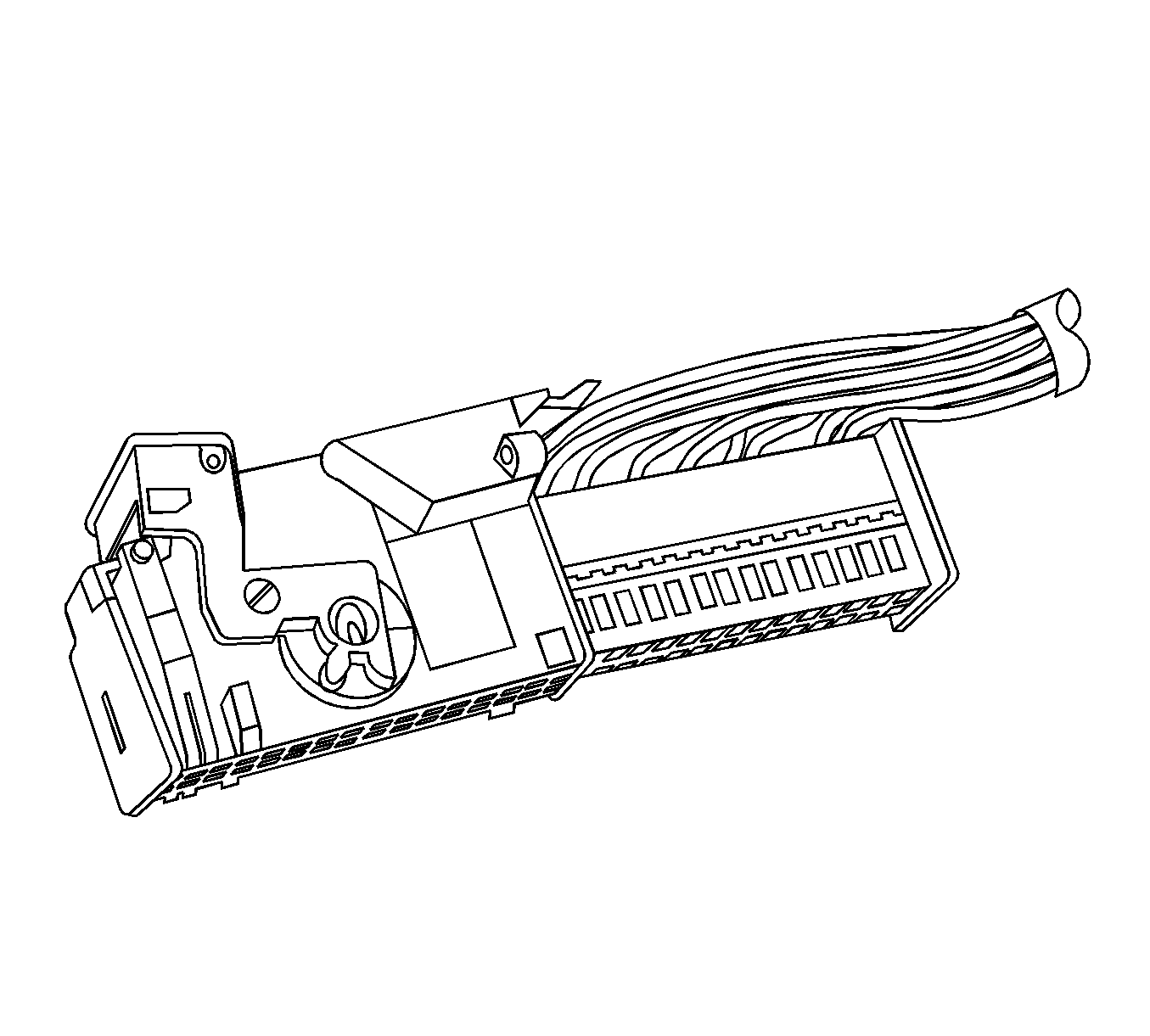
Tyco/AMP Connectors Door Module
Special Tools
J-38125 Terminal Repair Kit
Removal Procedure
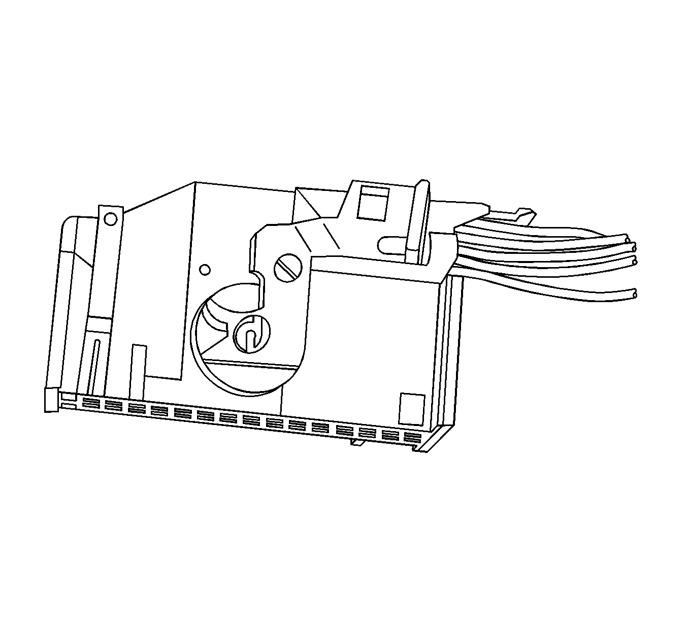
Side view of connector.
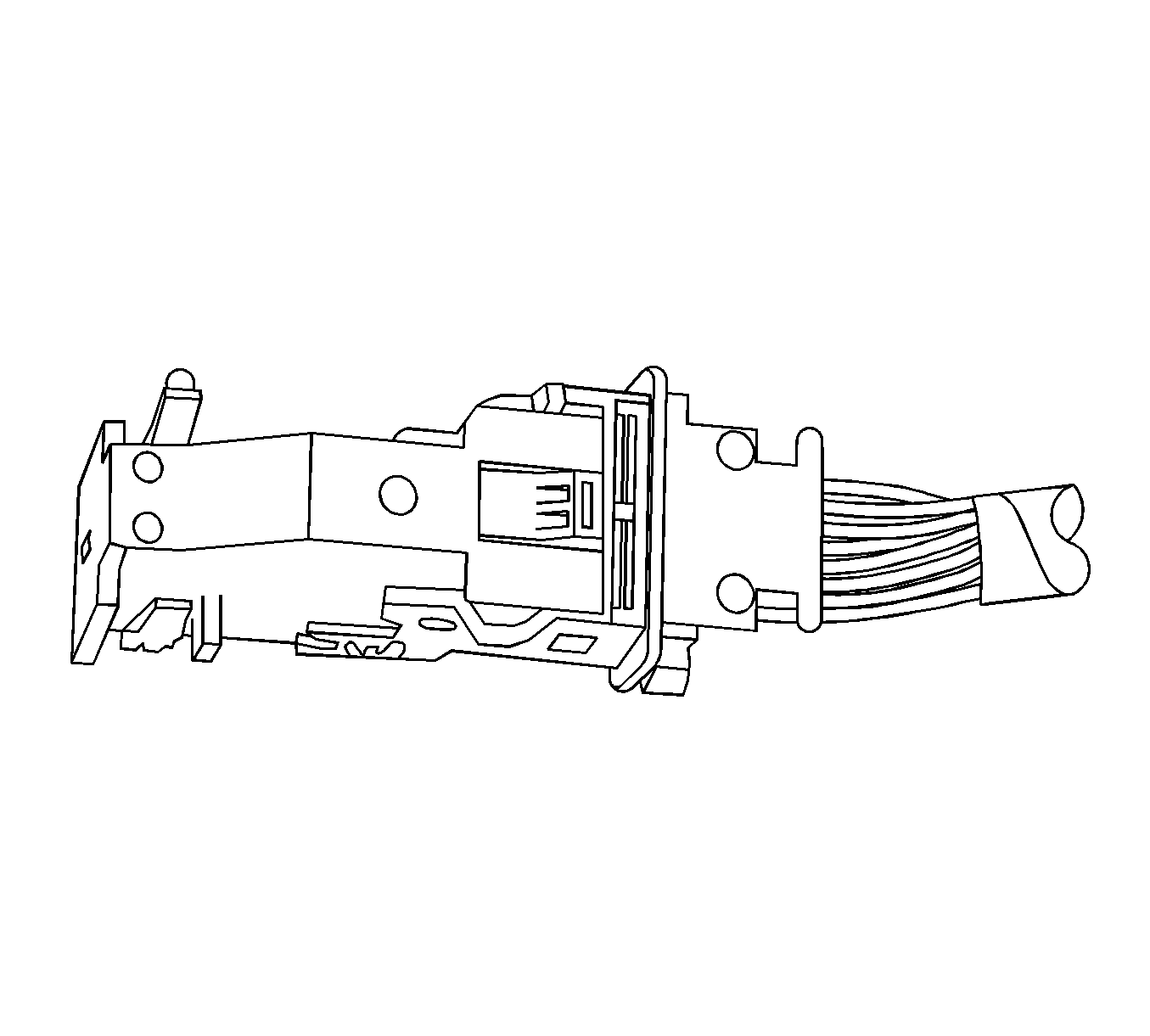
View of top of connector.
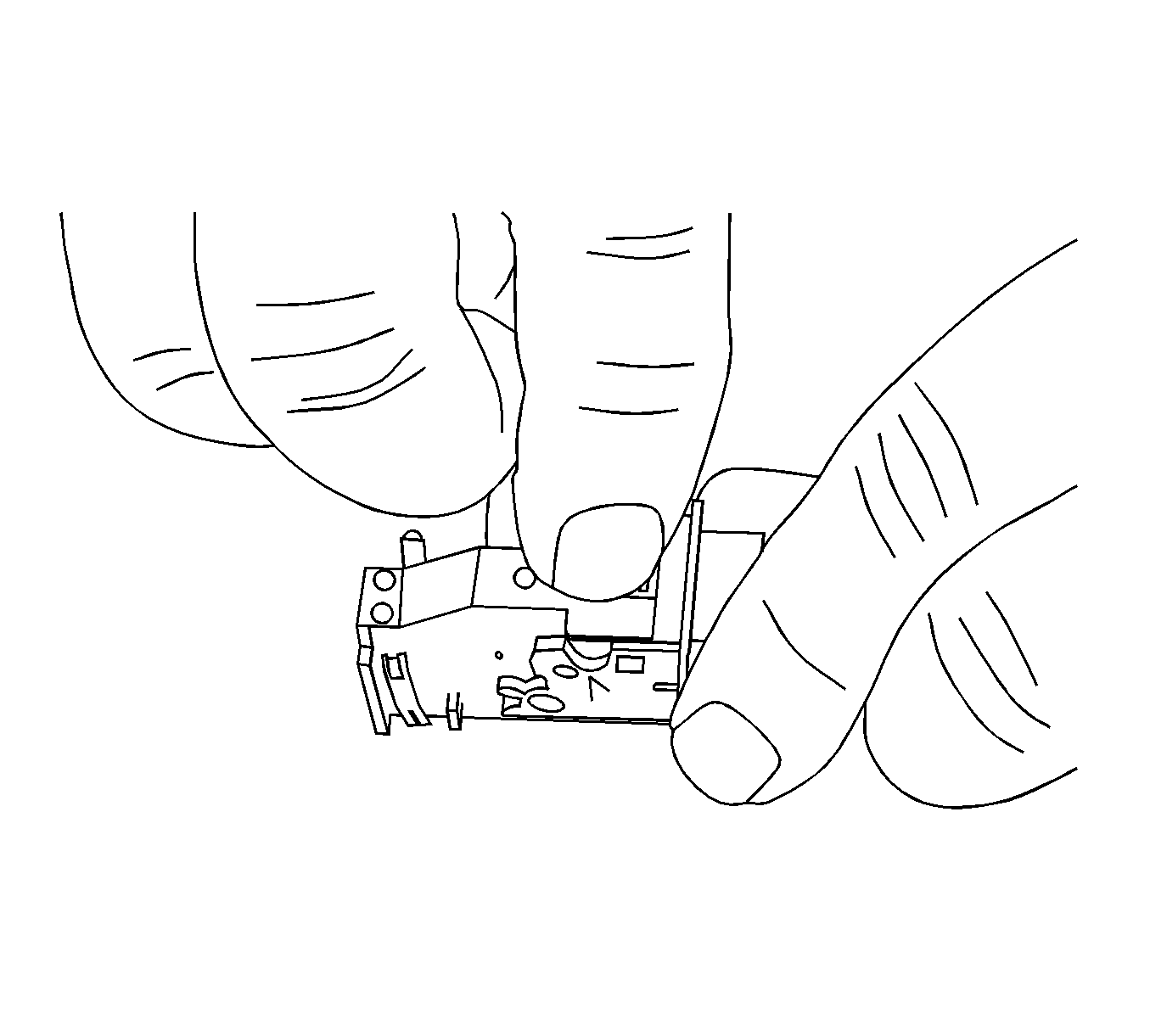
- Locate the assist lever and lock on the top of the connector.
- While depressing the lock, pull the lever over and past the lock.
- Disconnect the connector from the component.
- Locate the dress cover locking tabs at the rear of the connector. Use a small flat-blade tool to release the locking tabs. Repeat this procedure for the other locking tab.
- Once the locking tabs are unlocked, slide the inner connector out of the rear of the connector housing.
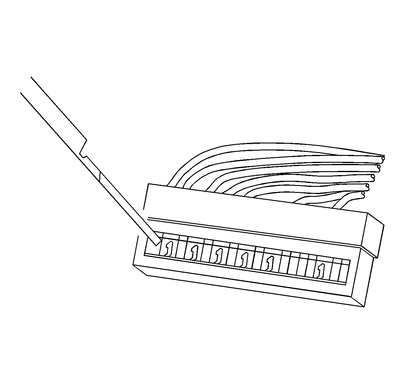
- Use the J 38125-12A tool to release the terminals by pressing on the tang. See the release tool cross reference in the Reference Guide of the J-38125 to ensure that the correct release tool is used.
- While holding the removal tool in place, gently pull the wire out of the back of the connector. Always remember never use force when pulling a terminal out of a connector.
Repair Procedure
Use the appropriate terminal and follow the instructions in the J-38125 .
Location of the terminal in the repair tray and the proper crimp tool can be found in the appropriate connector end view.
