For 1990-2009 cars only
Tools Required
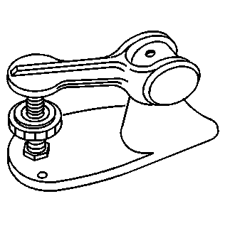
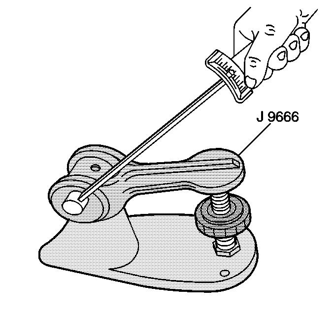
J 9666 Valve Spring Tester
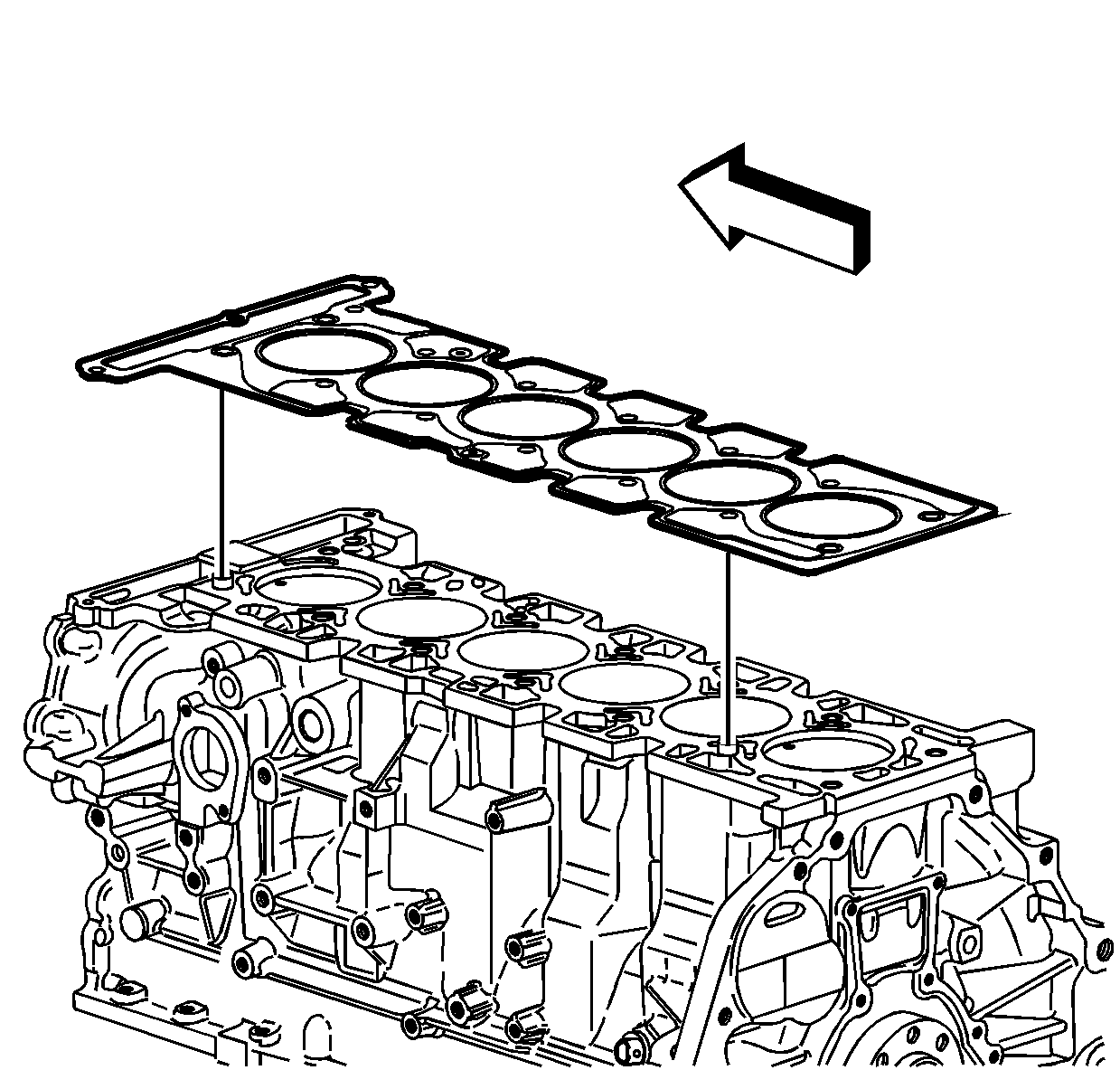
- Inspect the cylinder head gasket and the mating surface. Inspect for leaks, corrosion, and blowby.
- If the gasket failed, determine the cause. The following conditions may cause gasket failure:
- Clean the following components:
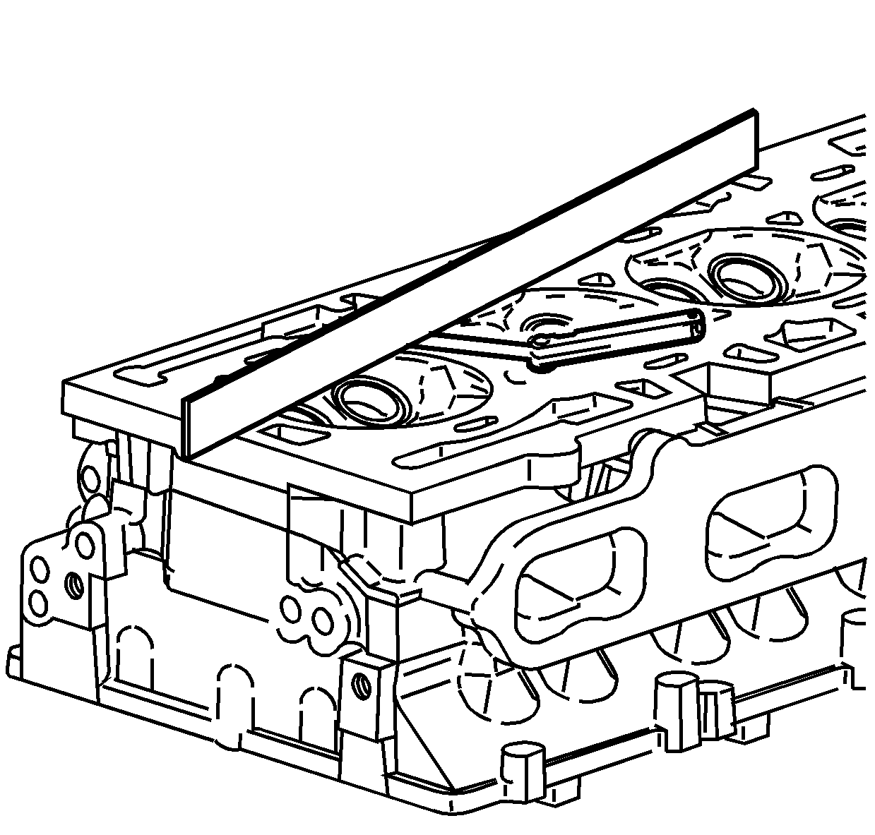
- Inspect the cylinder head mating surfaces for flatness. Use a feeler gauge and a straight edge.
- Replace the cylinder head if warped more than 0.08 mm (0.003 in).
- Inspect the cylinder head for cracks.
- Inspect the cylinder head deck for corrosion.
- Inspect the valve springs for squareness.
- Use J 9666 to measure the valve spring tension. Replace the valve spring if the tension is not within specification.
- Inspect the valve guides for wear. The valve guides may be reamed oversized 0.075 mm (0.003 in) and oversized stemed valves may be installed. The same size valve seal should be used.
- Inspect the valve seats for excessive wear, damage, or hot spots.
- Use the following procedure to measure the valve seat concentricity:
- Use the following procedure to measure the valve runout:
- Replace the head if the valve seats are damaged.
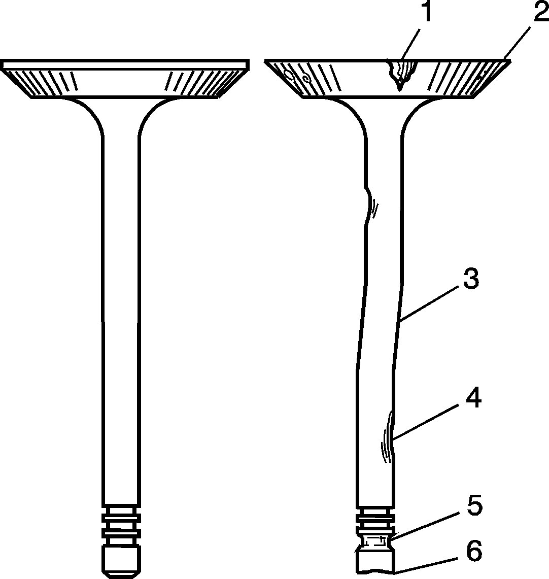
- Inspect the valves for the following damage:
| • | Improper installation |
| • | Warped cylinder head |
| • | Missing or not fully seated dowel pins |
| • | Low torque on the cylinder head bolts |
| • | Incorrect length cylinder head bolts |
| • | A warped engine block surface |
| • | Scratched surfaces |
| • | Foreign material |
| • | Cracked engine block threaded holes |
| • | The gasket surfaces |
| • | Do not use a motorized brush on the head gasket sealing surface. |
| • | Valve stems and valve heads |
| • | The bolt hole threads |
| • | Remove all dirt, debris, or threadlocking material from the bolt holes. |
Important: Do not attempt to weld the cylinder head. If the cylinder head is damaged, replace the cylinder head. Minor nicks may be repaired with a fine flat file or emery cloth.
| 12.1. | Lift the valve off the valve seat. |
| 12.2. | Apply a dab of blue dye to the valve face. |
| 12.3. | Seat and rotate the valve. The blue dye traces transferred to the valve seat are an indication of concentricity of the valve seat. |
| 13.1. | Clean off the blue dye. |
| 13.2. | Apply blue dye to the valve seat. |
| 13.3. | Seat and rotate the valve. |
| 13.4. | The traces of blue dye transferred to the valve indicates valve runout. |
| • | Grooving (1, 2) |
| • | Bent valve stem (3). Replace any bent valve. |
| • | Burrs or scratches (4). Minor burrs or scratches may be removed with a fine oil stone. |
| • | Chipped or worn key grooves (5). Replace if damaged. |
| • | Valve tip wear (6). Replace if worn. |
