Differential Carrier Assembly Replacement 4.2L In-Line Six Cylinder
Removal Procedure
- Remove the front tires and wheels. Refer to Tire and Wheel Removal and Installation.
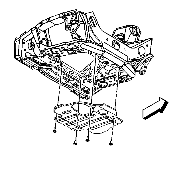
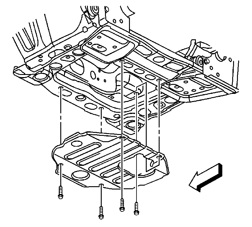
- Remove the engine protection shield. Refer to Engine Protection Shield Replacement.
- Drain the engine of oil.
- Drain the front drive axle. Refer to Front Axle Lubricant Replacement.
- Remove the front propeller shaft from the front axle. Refer to Front Propeller Shaft Replacement.
- Wrap the bearing caps with tape in order to prevent the loss of the roller bearings.
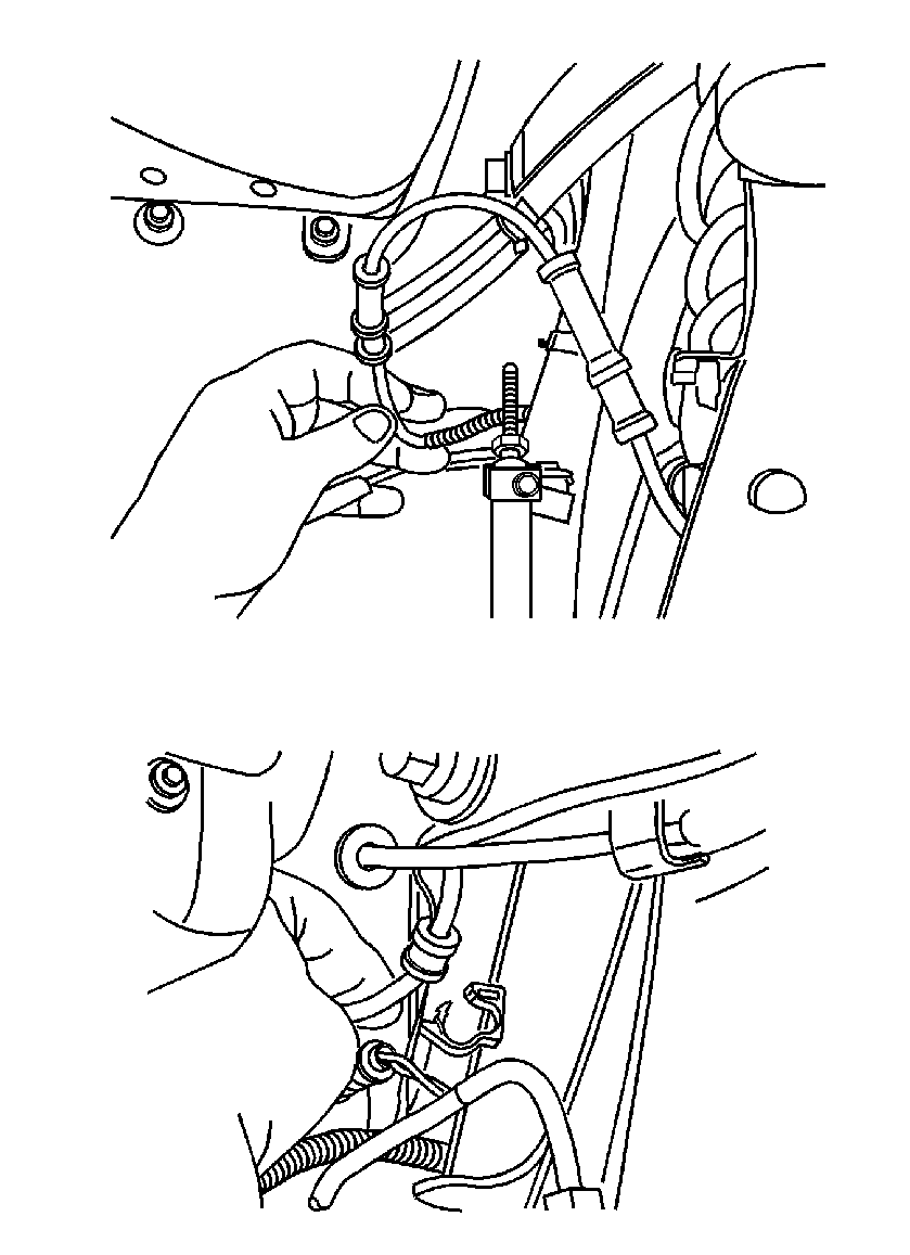
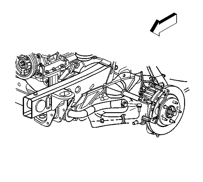
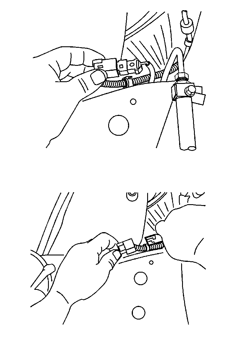
- Remove the antilock brake system (ABS) wiring harness from the retainers.
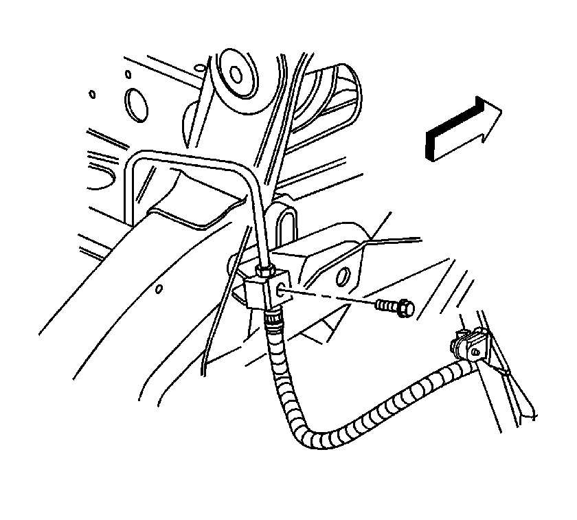
- Remove the brake hose retaining bolts.
- Remove the front drive axle vent hose.
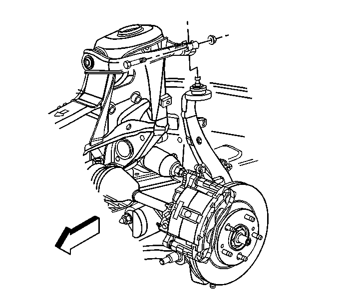
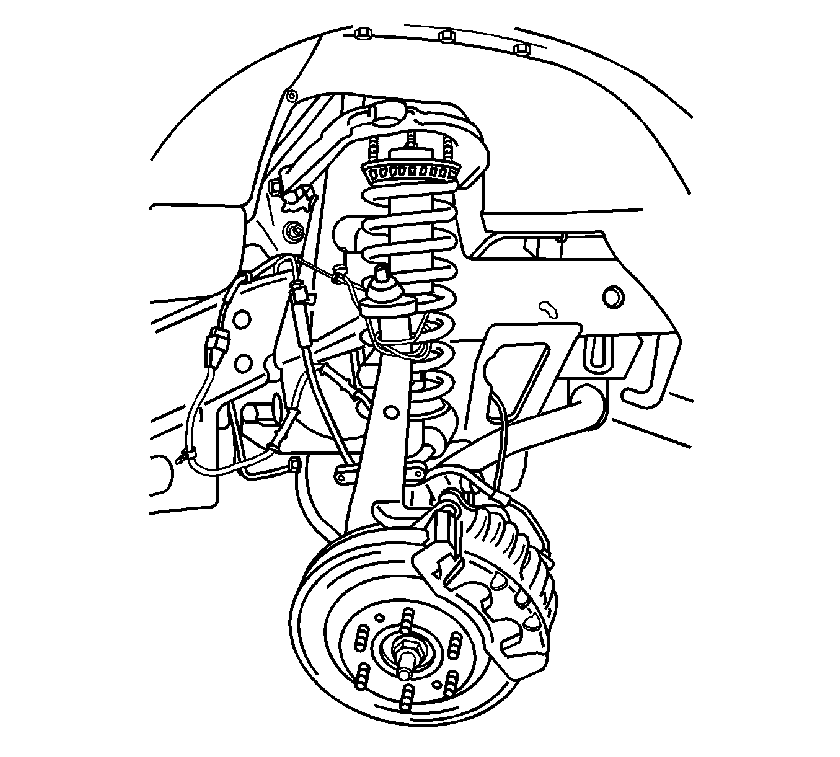
- Remove the left and right upper ball pinch bolt and nut.
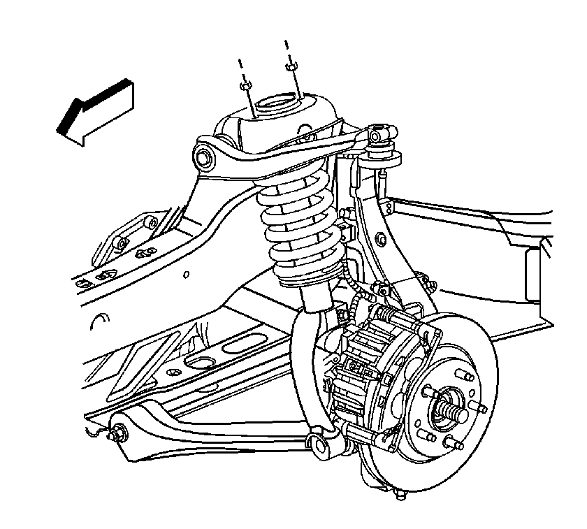
- Remove the left and right upper shock module retaining nuts.
- Remove the front stabilizer bar links from the frame. Refer to Stabilizer Shaft Link Replacement.
- Remove the shock module from the frame.
- Remove the steering knuckle from the upper control arm.
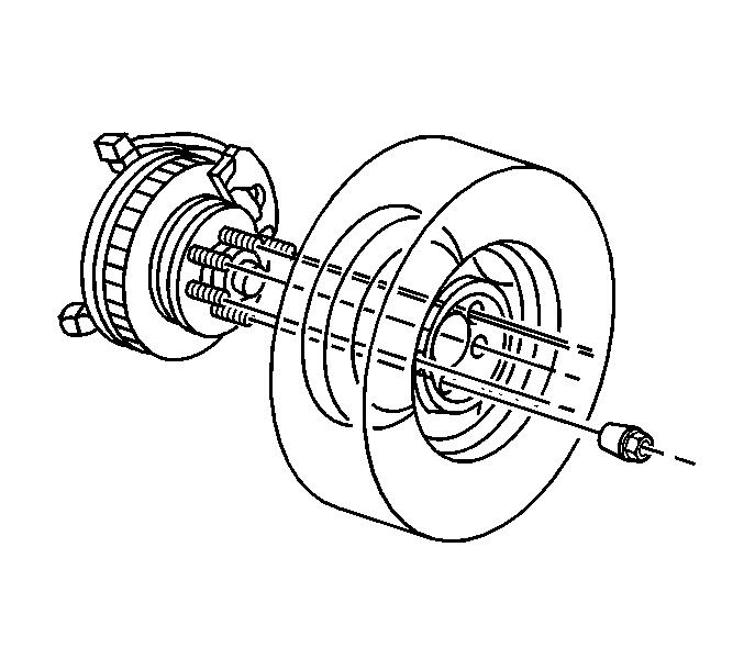
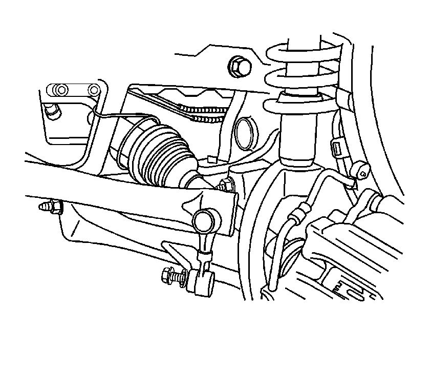
- Remove the left and right front wheel drive shafts from the front drive axle.
- Relocate and secure the left and right front wheel drive shafts to the frame.
- Using mechanics wire or hook, support the front shock modules and steering knuckle.
- Remove the power steering gear assembly. Refer to Steering Gear Replacement.
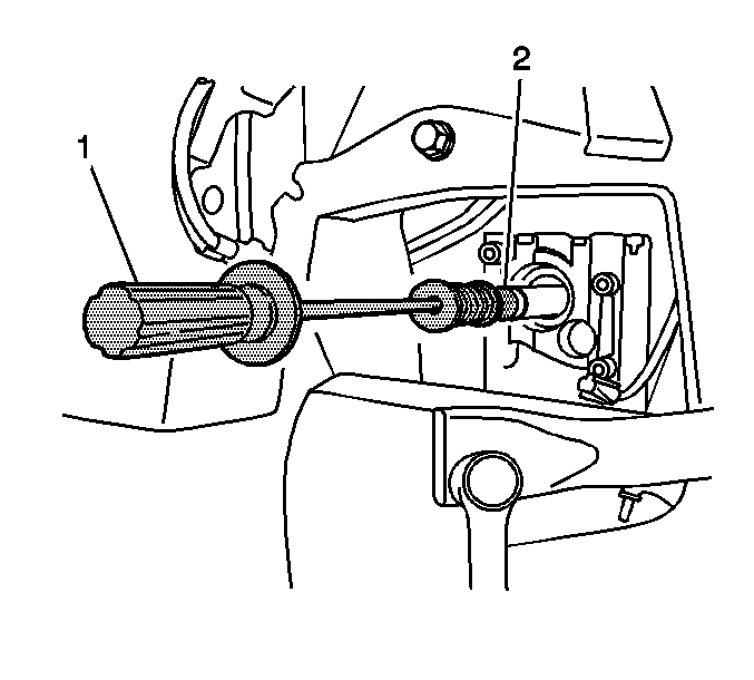
- Remove the inner shaft (2) from the front drive axle. Refer to Front Drive Axle Inner Shaft Replacement.
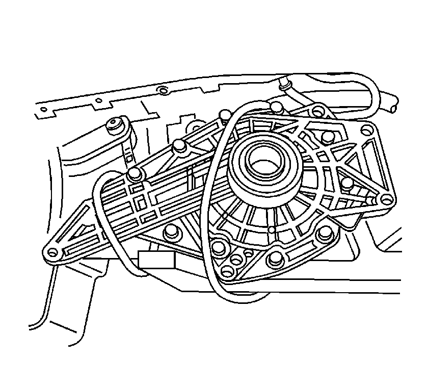
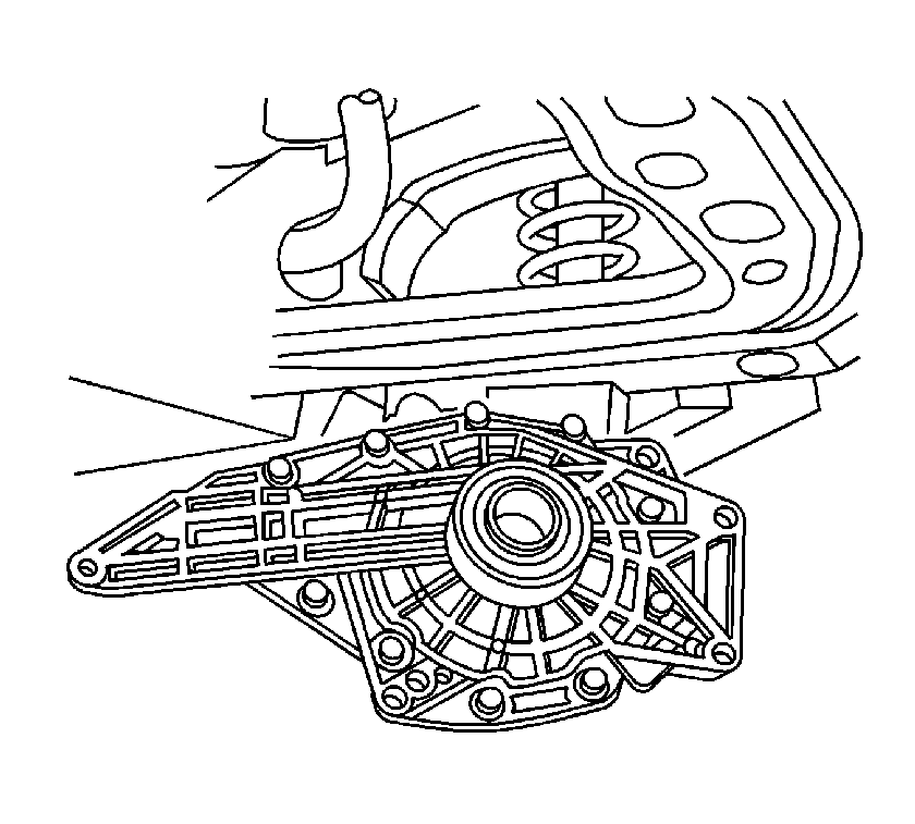
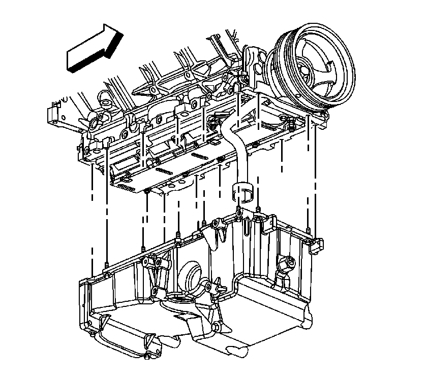
- Remove the front drive axle from the oil pan.
- Secure the front drive axle to the frame.
- Remove the oil pan. Refer to Oil Pan Replacement.
- Remove the front drive axle from the vehicle.
Installation Procedure
- Install the front drive axle to the frame.
- Secure the front drive axle to the frame.
- Install the oil pan. Refer to Oil Pan Replacement.
- Remove the front drive axle from the frame.
- Install the front drive axle to the oil pan.
- Install the front drive axle mounting bolts.
- Install the inner axle (2) to the front drive axle. Refer to Front Drive Axle Inner Shaft Replacement.
- Install the power steering gear. Refer to Steering Gear Replacement.
- Remove the left and right front wheel drive shafts from the frame.
- Remove the left and right shock module and steering knuckles from their supports.
- Install the right and left front wheel drive shafts to the front drive axle.
- Install the vent hose to the front drive axle.
- Install the left and right shock modules to the frame.
- Install the upper shock module retaining nuts.
- Install the steering knuckle to the upper control arm.
- Install the upper ball joint pinch bolt and nut.
- Install the front stabilizer bar links to the frame. Refer to Stabilizer Shaft Link Replacement.
- Install the brake hose retaining bolts.
- Install the right and left ABS wiring harness in the retainers.
- Install the front propeller shaft from the front axle. Refer to Front Propeller Shaft Replacement.
- Fill the front drive axle with the proper fluid. Refer to Front Axle Lubricant Replacement.
- Fill the engine with the proper amount motor oil. Refer to Approximate Fluid Capacities.
- Install the engine protection shield. Refer to Engine Protection Shield Replacement.
- Install the tires and wheels. Refer to Tire and Wheel Removal and Installation.
Caution: Refer to Fastener Caution in the Preface section.
Tighten
Tighten the front drive axle mounting bolts to 85 N·m (63 lb ft).
Tighten
Tighten the upper shock module mounting bolts to 100 N·m (74 lb ft).
Tighten
Tighten the upper shock module mounting bolts to 40 N·m (30 lb ft).
Tighten
Tighten the brake hose retaining bolt to 25 N·m (18 lb ft).
Differential Carrier Assembly Replacement 5.3L V-8
Removal Procedure
- Remove the tire and wheel assembly. Refer to Tire and Wheel Removal and Installation.
- Remove the engine protection shield. Refer to Engine Protection Shield Replacement.
- Drain the front differential. Refer to Front Axle Lubricant Replacement.
- Remove the left and right antilock brake system (ABS) wiring harnesses from the retainers.
- Disconnect the left and right wheel speed sensor electrical connectors.
- Remove the brake hose retaining bolt from the frame.
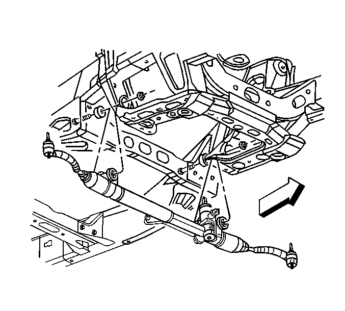
- Disconnect the sway bar link pins from the lower control arms.
- Remove the steering gear. Refer to Steering Gear Replacement.
- Place an adjustable jack stand under the lower control arm.
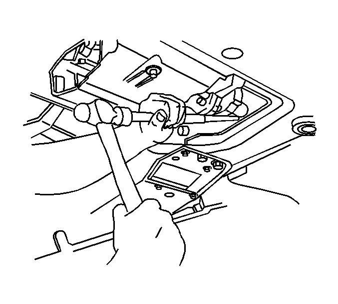
- Remove the upper ball joint pinch bolt and nut.
- Remove the steering knuckle from the upper control arm.
- Remove the upper shock module bolts from the frame.
- Lower the jack stand to allow removal of the steering knuckle from the upper control arm.
- Remove the steering knuckle from the upper control arm.
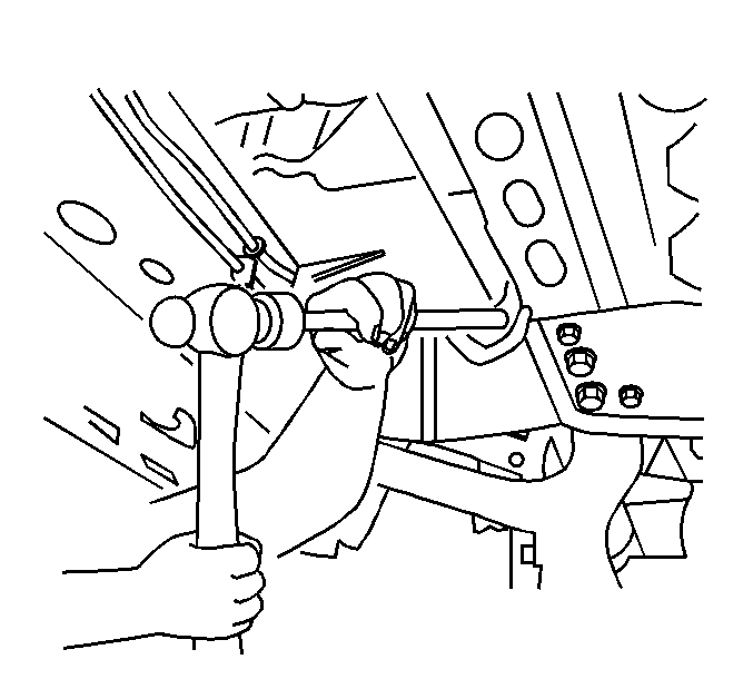
- Using a brass drift or equivalent, remove the left wheel drive shaft from the front differential.
- Using a brass drift or equivalent, remove the right wheel drive shaft from the front differential.
- Position the wheel drive shafts to the side.
- Using mechanics wire or metal hooks, secure the shock modules to the frame.
- Remove the jack stand.
- Remove the front propeller shaft from the front pinion yoke. Refer to Front Propeller Shaft Replacement.
- Relocate the propeller shaft to the side and secure.
- Remove the inner axle shaft (2). Refer to Front Drive Axle Inner Shaft Replacement.
- Remove the mounting bolts for the front differential assembly.
- Remove the front differential assembly from the oil pan.
- Secure the front differential to the frame.
- Remove the oil pan assembly. Refer to Oil Pan Replacement.
- Remove the front differential from the vehicle.
Note: In the following service procedures, it is not necessary to remove the wheel drive shaft from the steering knuckles.
Note: DO NOT allow the shock modules and steering knuckle to hang without supporting them.
Note: It is not necessary to completely remove the front propeller shaft from the vehicle.
Installation Procedure
- Position the front differential assembly on the frame.
- Secure the front differential assembly.
- Install the oil pan assembly. Refer to Oil Pan Replacement.
- Position the front differential on the oil pan.
- Install the differential bolts.
- Install the inner axle shaft. Refer to Front Drive Axle Inner Shaft Replacement.
- Position the adjustable jack stand under the lower control arm.
- Remove the shock module from the secure position.
- Install the right wheel drive shaft in the inner drive shaft.
- Rinse the jack stand to allow the installation of the steering knuckle in the upper control arm.
- Install the upper ball joint pinch nut and bolt.
- Remove the jack stand from under the lower control arm.
- Install the front shock upper retaining nuts.
- Install the steering rack assembly. Refer to Steering Gear Replacement.
- Install the brake hose retaining bolt.
- Install the sway bar links to the lower control arm. Refer to Stabilizer Shaft Link Replacement.
- Connect the wheel speed sensors electrical connectors.
- Install the left and right ABS wiring harnesses in the retainers.
- Install the front propeller shaft. Refer to Front Propeller Shaft Replacement.
- Fill the front differential with fluid. Refer to Front Axle Lubricant Replacement.
- Install the engine protection shield. Refer to Engine Protection Shield Replacement.
- Install the tires and wheels. Refer to Tire and Wheel Removal and Installation.
Caution: Refer to Fastener Caution in the Preface section.
Tighten
Tighten the bolts to 85 N·m (63 lb ft).
Tighten
Tighten the bolt and nut to 40 N·m (30 lb ft).
Tighten
Tighten the nuts to 45 N·m (33 lb ft).
Tighten
Tighten the brake hose retaining bolt to 25 N·m (18 lb ft).
