Tools Required
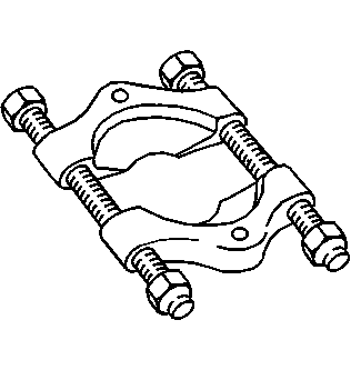
| • | J 22912-B Split-Plate Bearing Puller |
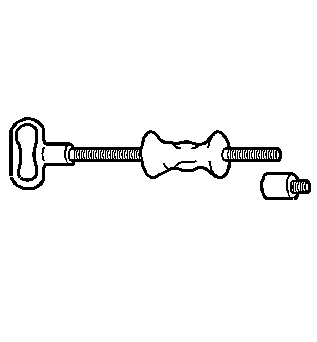
| • | J 2619-01 Slide Hammer with Adapter |
| • | J 29369-1 Bushing and Bearing Remover |
| • | J 29369-2 Bushing and Bearing Remover (2"-3") |
| • | J 42213 Adjuster Sleeve Socket |
| • | J 45224 Side Bearing Adjustment Wrench |
| • | J 45228 Pinion Bearing Cup Remover/Installer |
| • | J 45234 Pinion Remover |
| • | J 8614-01 Flange and Pulley Holding Tool |
Inspection Procedure
Perform the following before disassembling the differential carrier assembly:
- Remove the drain plug from the axle.
- Drain the axle lubricant.
- Inspect the oil and the case for metal chips.
- Inspect the ring gear backlash. Refer to Backlash Inspection and Adjustment .
- Measure the rotating torque of the pinion and differential case using an inch-pound torque wrench.
Determine the source of the metal chips, such as a broken gear or bearing cage.
This information can be used in order to determine the cause of the axle problem. The information will also help when setting up and preloading the differential case.
Determine the cause of the axle problem before disassembly, if possible.
Disassembly Procedure
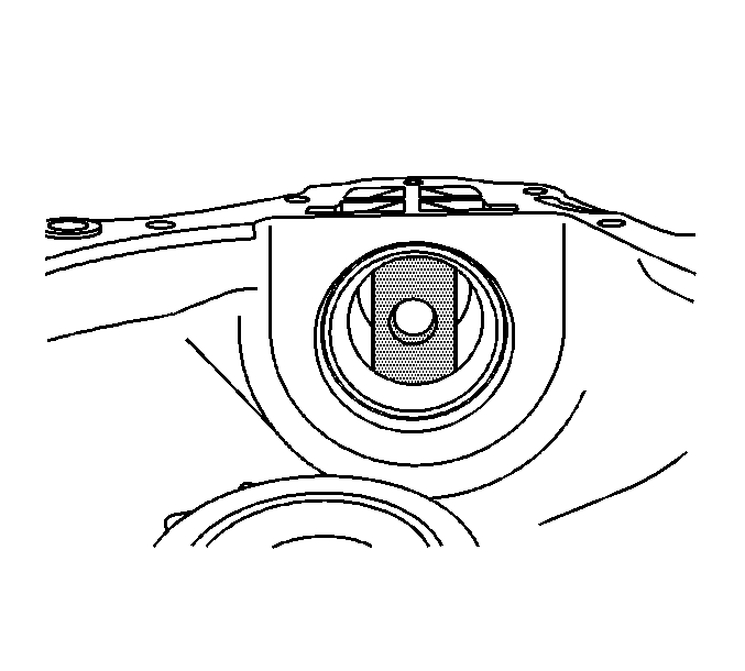
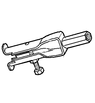
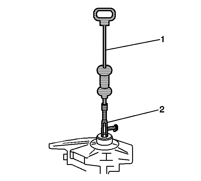
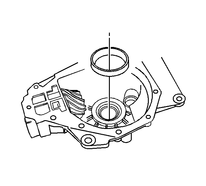
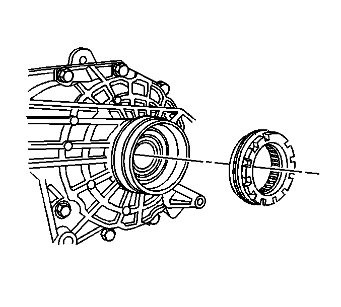
- Install the J 29369-1 (2) and the J 2619-01 (1) to the inboard or oil pan side seal as shown.
- Remove the seal by pulling on the J 2619-01 (1).
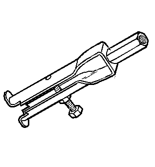
- Install the J 29369-2 and the J 2619-01 to the outboard or wheel drive shaft side seal.
- Remove the seal by pulling on the J 2619-01 .
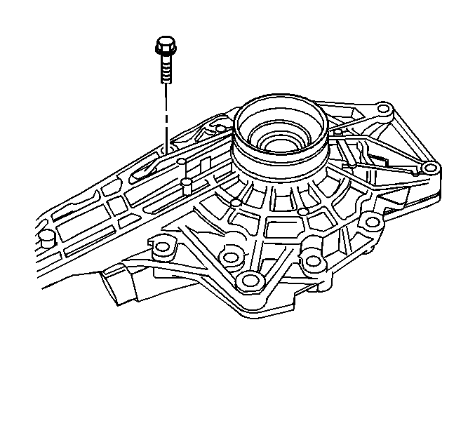
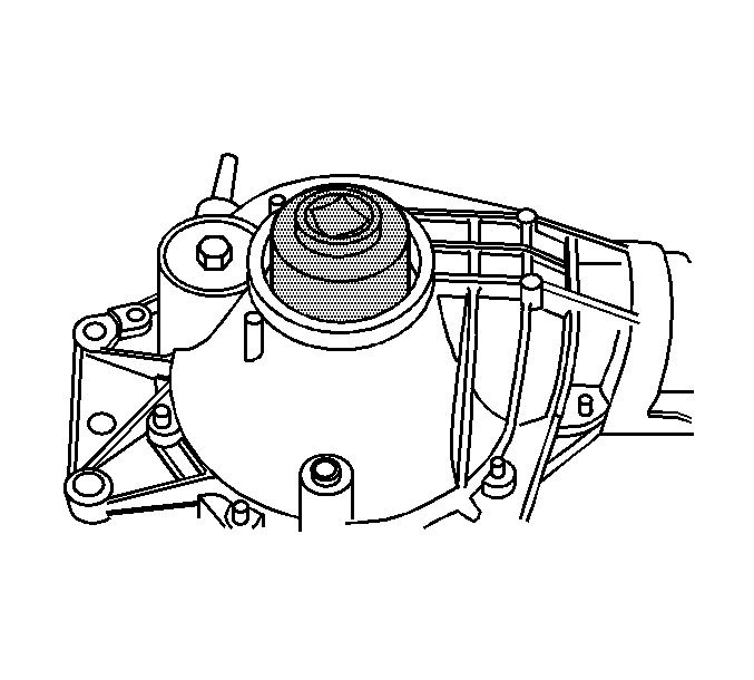
- Remove the differential carrier case half bolts.
- Separate the differential carrier case assembly case halves.
- Remove the differential case assembly.
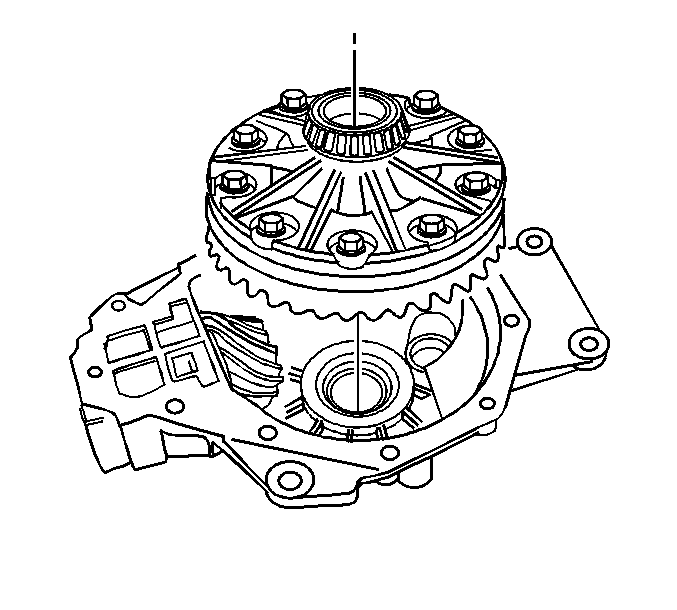
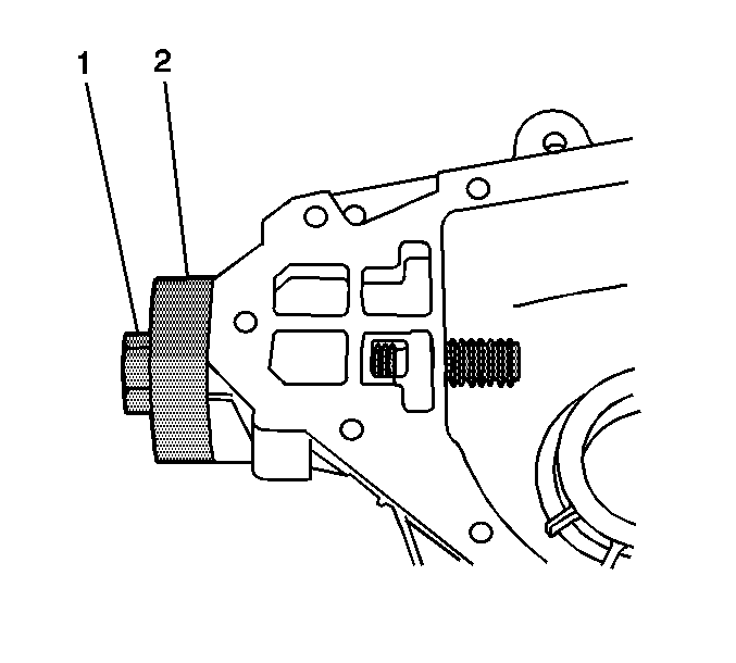
- Install the J 42213 to the left side differential bearing adjuster.
- Remove the left side differential bearing adjuster using the J 42213 .
- Remove the left side differential bearing cup.
- Install the J 45224 to the right side differential bearing adjuster.
- Remove the right side differential bearing adjuster using the J 45224 . Mark the adjuster.
- Remove the right side differential bearing cup.
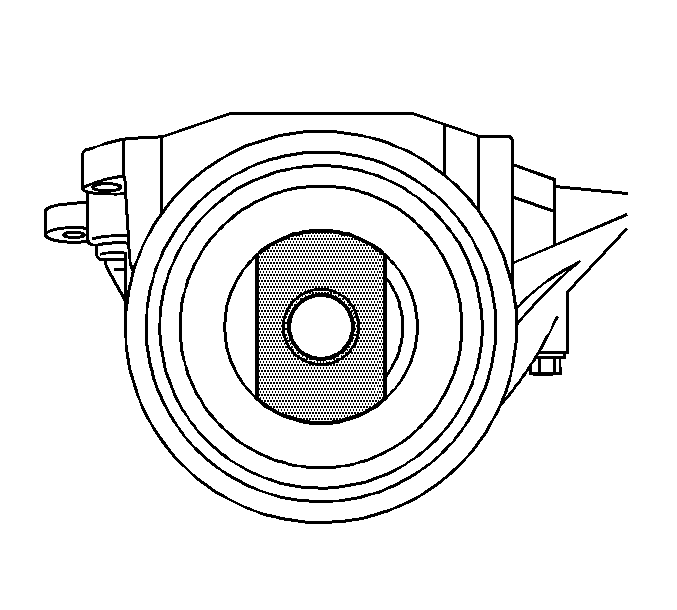
- Measure the rotating torque of the drive pinion using an inch-pound torque wrench. Record the measurement.
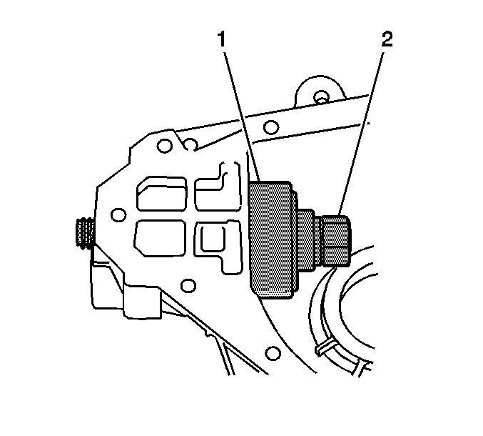
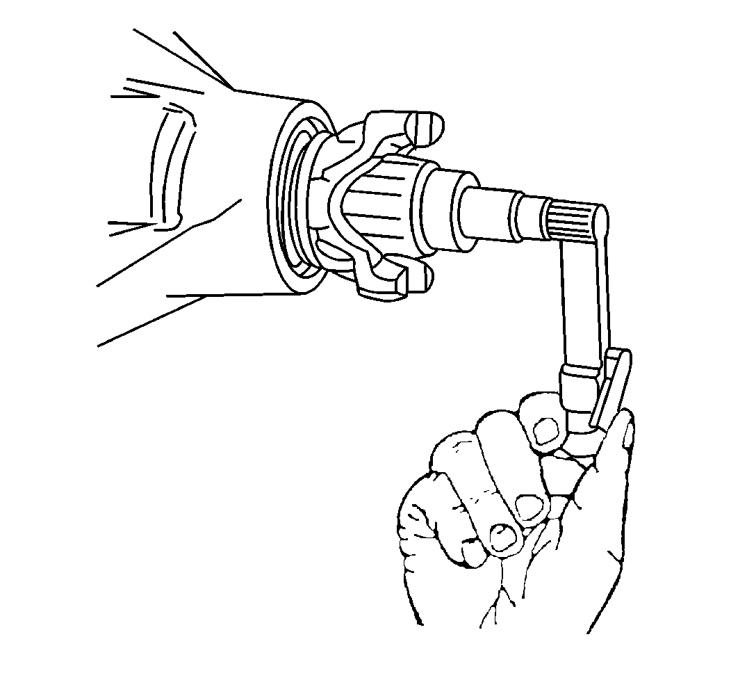
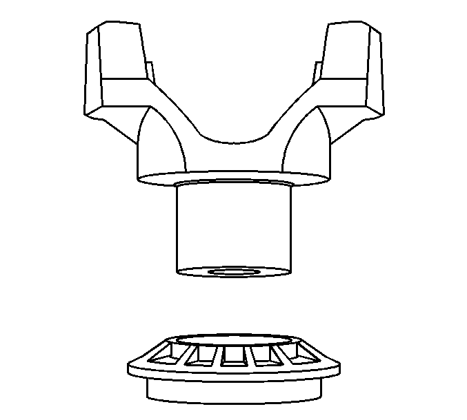
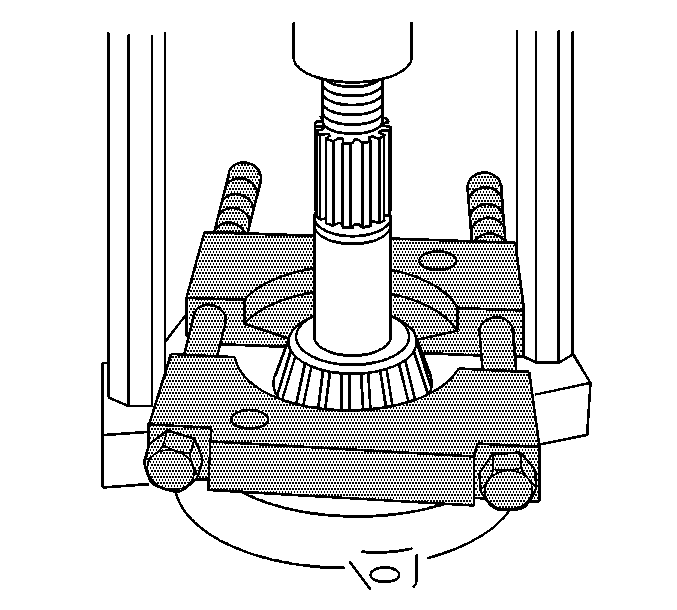
- Install the J 8614-01 to the pinion yoke as shown.
- Remove the pinion nut while holding the J 8614-01 .
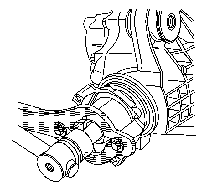
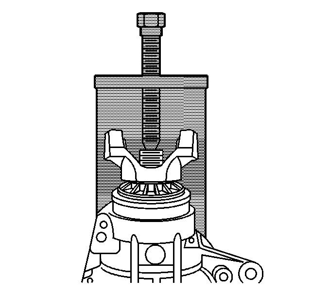
- Install the J 45234 to the left differential carrier assembly case half as shown.
- Remove the pinion yoke, the washer, and the drive pinion by turning the screw of the J 45234 clockwise.
- Remove the dust deflector from the pinion yoke with a soft-faced hammer.
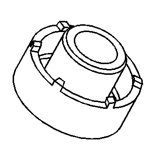
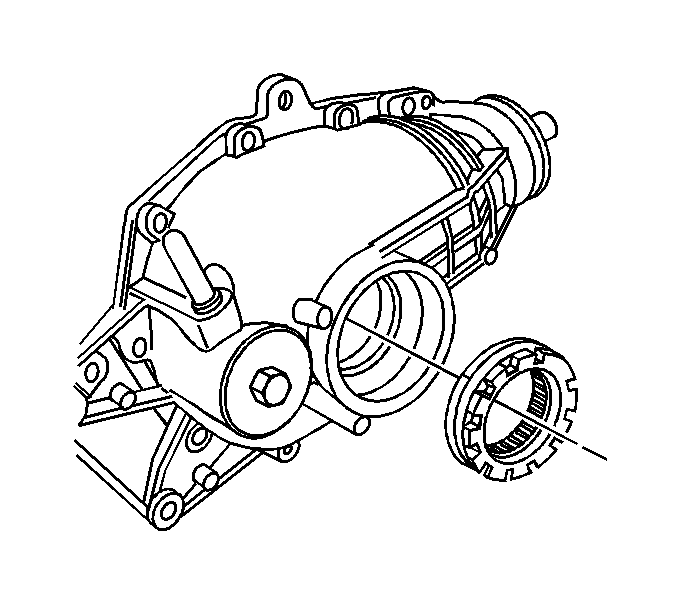
- Remove the pinion oil seal using a suitable seal remover tool.
- Remove the outer pinion bearing.
- Install the J 22912-B between the pinion bearing and the pinion gear as shown.
- Remove the inner pinion bearing using the J 22912-B and a hydraulic press.
- Remove the pinion gear selectable shim.
- Install the J 45228-4 to the outer pinion bearing cup as shown.
- Install the J 45228-1 (2) and the J 45228-5 (1) to the J 45228-4.
- Remove the outer pinion bearing cup by turning the J 45228-5 (1) clockwise.
- Install the J 45228-4 to the inner pinion bearing cup as shown.
- Install the J 45228-1 (1) and the J 45228-5 (2) to the J 45228-4.
- Remove the outer pinion bearing cup by turning the J 45228-5 (2) clockwise.
Important: The differential bearing adjusters are not interchangeable. Mark the adjusters accordingly.
Mark the adjuster.
Important: The differential bearing adjusters are not interchangeable. Mark the adjusters accordingly.
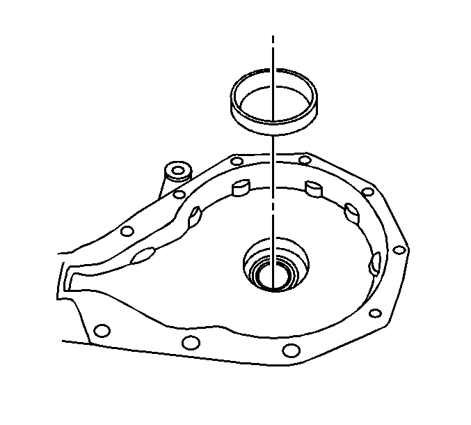
Important: Carefully pry the seal from the bore. Do not distort or scratch the aluminum case.
Seat the ridge of the J 45228-1 (2) into the outer pinion bearing cup bore.