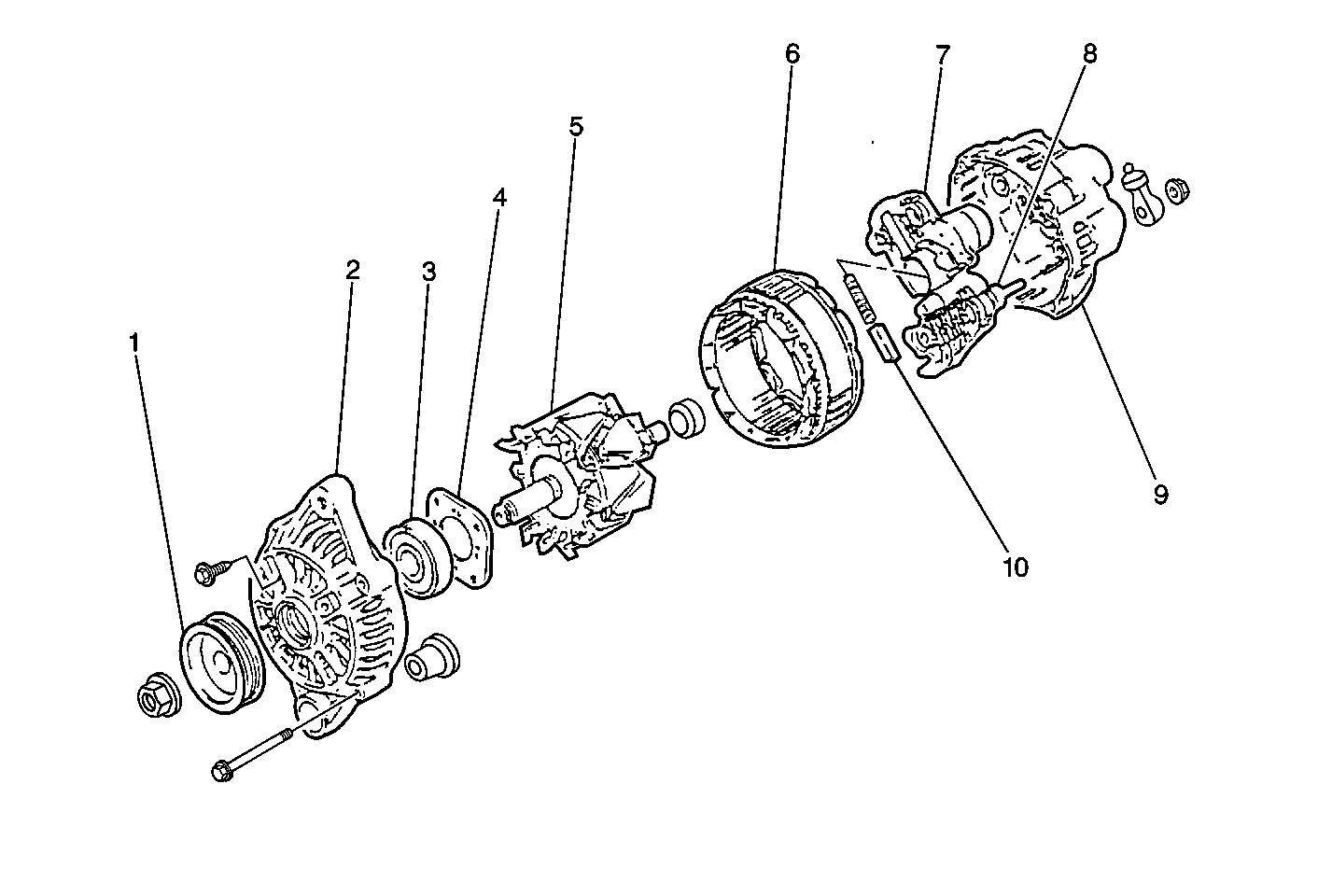
The generators are non-repairable and are electrically similar to earlier models. The generators feature the following major components:
The pulley and the fan cool the slip ring and the frame.
Three generators are used, rated at 60, 70 and 85 amperes.
The generators feature permanently lubricated bearings. Service should only include tightening of mounting components. Otherwise, the generator is replaced as a complete unit.
The voltage regulator controls the rotor field current in order to limit the system voltage. When the field current is on, the regulator switches the current on and off at a rate of 400 cycles per second in order to perform the following functions:
At high speeds, the on-time may be 10 percent with the off-time at 90 percent. At low speeds, the on-time may be 90 percent and the off-time 10 percent.
Neutral diodes are used to convert the voltage fluctuation at the neutral point to DC current in order to increase generator output on the 70 and 85 ampere models.
The charging system indicator illuminates when the following occurs:
When the ignition switch is turned to the ON position and the generator is not rotating, the regulator provides a ground which causes a bulb check and the charge indicator illuminates. When the generator is rotating, the regulator provides a separate output voltage to the charge indicator. Since equal voltage is now provided to both sides of the charge indicator, the lamp loses its ground and goes out.
The generator provides voltage to operate the vehicle's electrical system and to charge its battery. A magnetic field is created when current flows through the rotor. This field rotates as the rotor is driven by the engine, creating an AC voltage in the stator windings. The AC voltage is converted to DC by the rectifier bridge and is supplied to the electrical system at the battery terminal.
When the engine is running, and the generator is rotating, a voltage is generated in the stator. The generator's voltage regulator senses this voltage and controls current to the rotor, thereby controlling the output voltage. The rotor current is proportional to the electrical pulse width supplied by the regulator. When the engine is started, the regulator senses generator rotation by detecting AC voltage at the stator through an internal wire. Once the engine is running, the regulator varies the field current by controlling the pulse width. This regulates the generator output voltage for proper battery charging and electrical system operation.
The generator F terminal is connected internally to the voltage regulator. When the voltage regulator detects a charging system malfunction, it grounds this circuit which illuminates the charge indicator lamp. The system voltage sense circuit receives ignition voltage through the IG fuse in the junction block. This voltage is used by the regulator as the reference for system voltage control.