Removal Procedure
- Disconnect the negative battery cable.
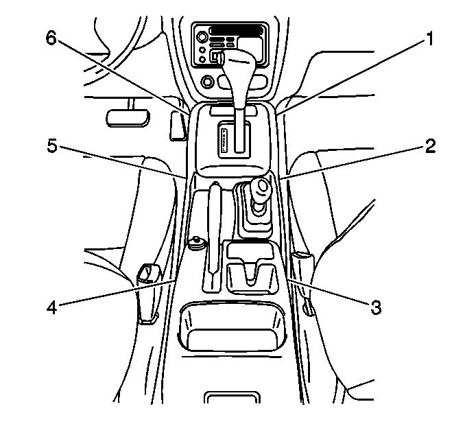
- Remove the rear console screws (3,4) and the console.
- Remove the center console screws (1,6) and the clips (2,5).
- Remove the center front console while disconnecting the electrical connector.
- Remove the transfer case boot cover screws.
- Remove the transfer case boot cover and the #2 boot (2) .
- Remove the transfer case shift boot clamp, the #1 boot, and the transfer case assembly.
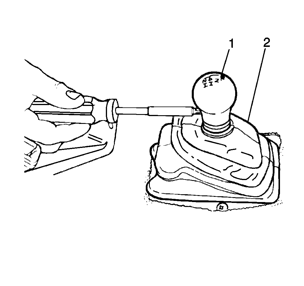
- Remove the 1 screw (1) and the gear shift control lever knob from the gear shift control lever.
- Remove the throttle body bolt and bracket (2).
- Remove the T.V. cable from the throttle body linkage and unroute the cable from the upper part of the engine.
- Remove the fluid indicator.
- Remove the upper starter bolts (3) and the starter nuts.
- Set aside the ground wire (1).
- Raise and properly support the vehicle. Refer to Lifting and Jacking the Vehicle in General Information.
- Drain the transfer case (2).
- Remove the front propeller shaft. Refer to Front Propeller Shaft Replacement .
- Remove the rear propeller shaft. Refer to Rear Propeller Shaft Replacement .
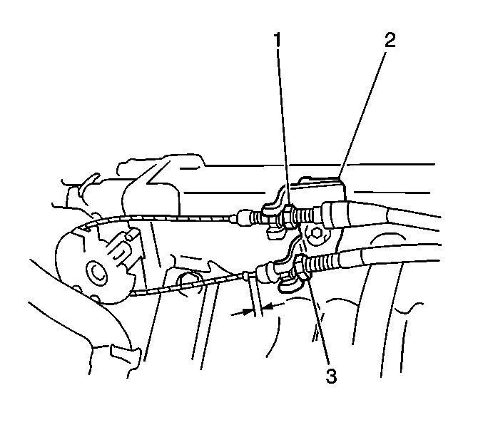
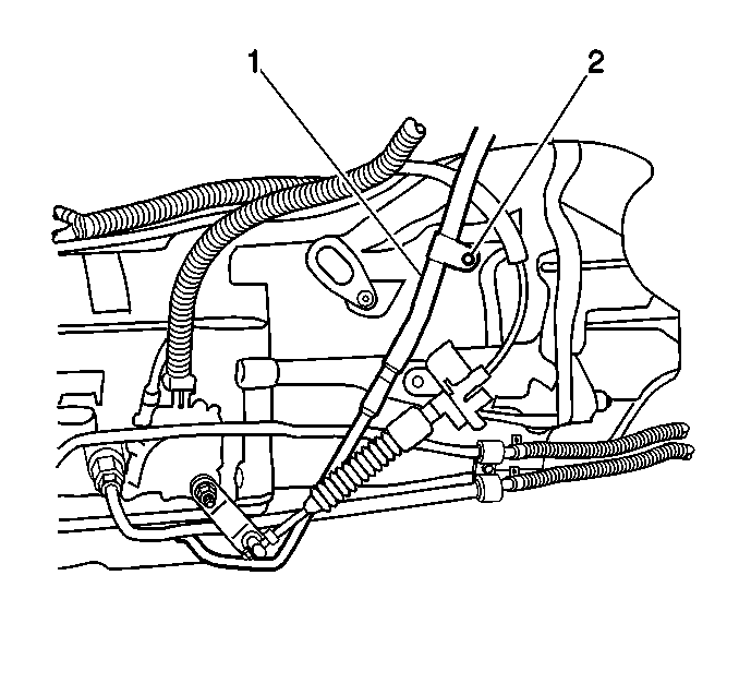
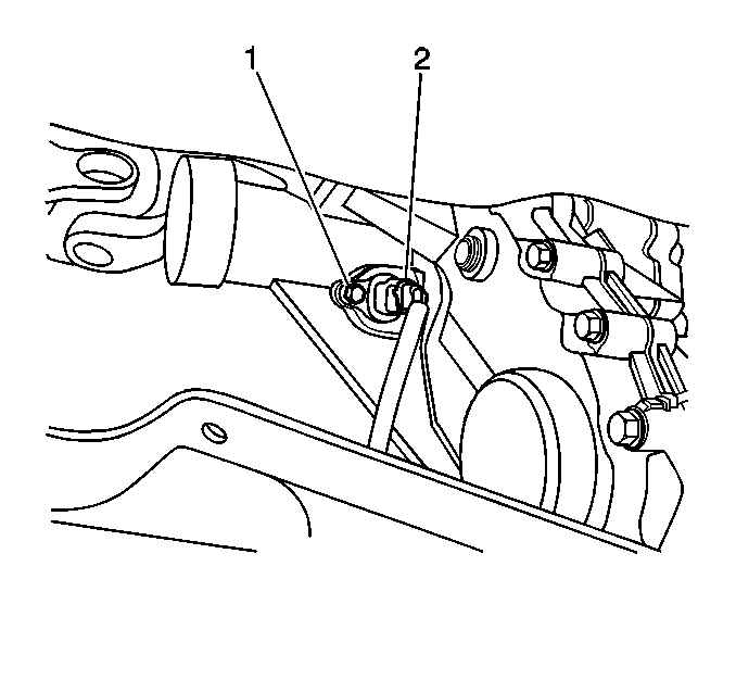
- Remove the shift cable retainer (4) and the cable (3) from the cable bracket (1).
- Remove the shift cable from the manual lever (2).
- Remove the shift cable bracket bolts and the bracket from the transmission.
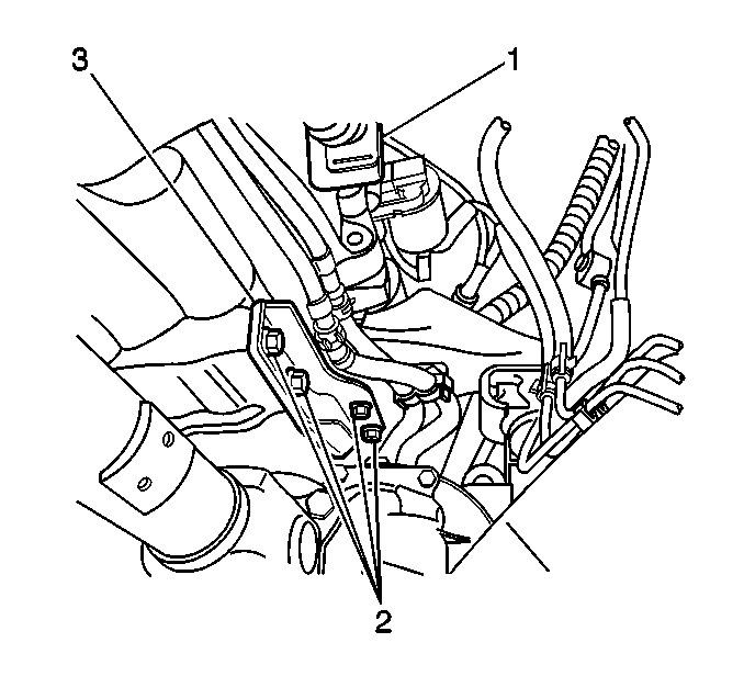
- Remove the fluid indicator tube bolt (2).
- Remove the fluid indicator tube and the O-ring seal.
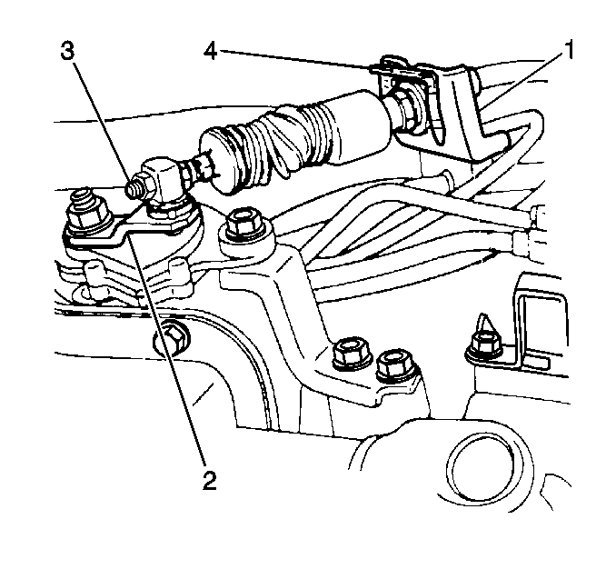
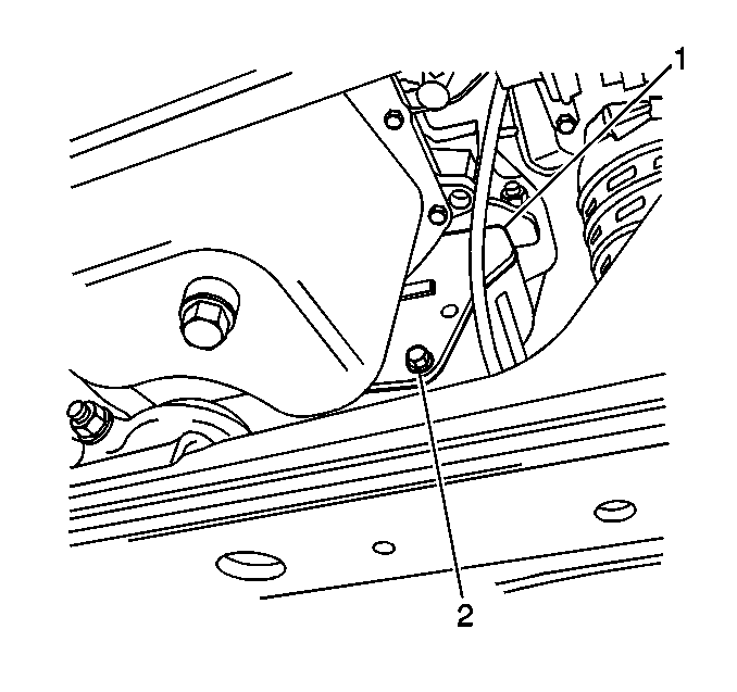
- Remove the bolts (2) which secure the right side transmission to the engine brace. Remove the brace (3).
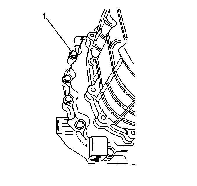
- Remove the flywheel inspection cover bolts (2) and the cover (1).
- Remove the torque converter bolts.
- Remove the lower bell housing bolts.
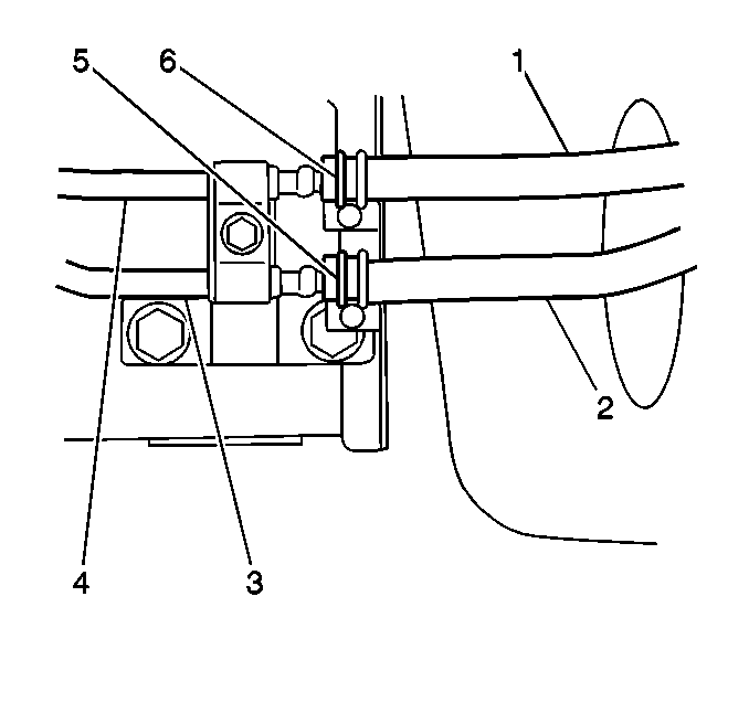
- Remove the cooler hoses (1,2) and the clamps (5,6) from the transmission pipes (3,4).
- Remove the transfer case skid plate bolts (1,4) and the skid plate (2).
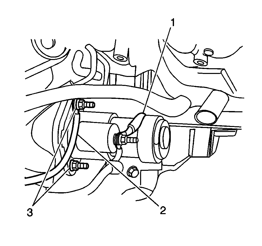
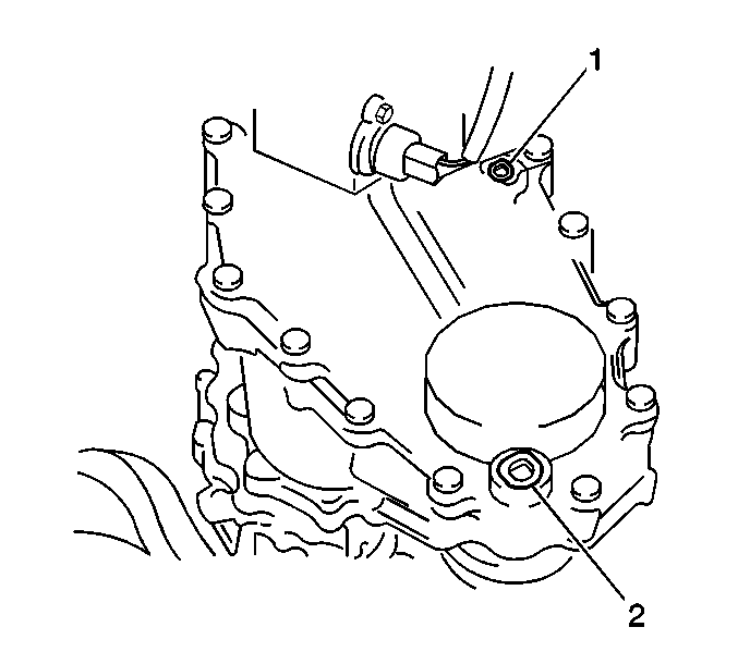
- Remove the VSS bolt (1) and the VSS from the transfer case.
- Remove the ground wire bolt and the wire from the transfer case mount.
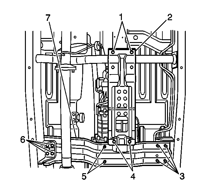
- Remove the 10 crossmember bolts (3,5,6) and the crossmember (7).
- Disconnect the transmission and transfer case electrical connectors.
- Disconnect the vent tubes.
- Remove the transmission wire harness, the retainer bolt, and the retainer.
- With the aide of an assistant, remove the transfer case bolts (1) and the transfer case.
- Remove the upper bell housing bolts.
- Remove the transmission
Caution: Unless directed otherwise, the ignition and start switch must be in the OFF or LOCK position, and all electrical loads must be OFF before servicing any electrical component. Disconnect the negative battery cable to prevent an electrical spark should a tool or equipment come in contact with an exposed electrical terminal. Failure to follow these precautions may result in personal injury and/or damage to the vehicle or its components.
Installation Procedure
- Install the transmission by using a hydraulic jack.
- Install upper bell housing bolts (1).
- With the aide of an assistant, install the transfer case and the bolts (1).
- Install the transmission wire harness, the retainer, and the bolt.
- Connect the electrical connectors and the vent tubes to the transmission and the transfer case.
- Install the crossmember (7) and the crossmember bolts (3,5,6).
- Install the ground wire and the ground wire bolt to the transfer case mount.
- Install the VSS (2) and the VSS bolt (1) to the transfer case.
- Install the transfer case skid plate (2) and the bolts (1,4).
- Remove the jack from the transmission.
- Install the cooler hoses (1,2) and the clamps (5,6) to the transmission cooler pipes (3,4).
- Install the lower bellhousing nuts.
- Install the torque converter bolts.
- Install the flywheel inspection cover plate (1) and the bolts (2).
- Install the engine brace (3) and the bolts (2) to the right side of the transmission.
- Install the starter and the lower bolt.
- Connect the starter electrical connections (1,3).
- Install the fluid indicator tube (1), the bolt (2), and the O-ring seal.
- Install the shift cable bracket and the bolts.
- Install the shift cable to manual lever (2).
- Install the shift cable and retainer (4) to the cable (3) bracket (1).
- Install the front propeller shaft. Refer to Front Propeller Shaft Replacement .
- Install the rear propeller shaft. Refer to Rear Propeller Shaft Replacement .
- Fill the transfer case (1). Refer to Oil Replacement .
- Lower the vehicle.
- Install the upper starter bolt, the nut, and the ground wire.
- Install the fluid level indicator.
- Route the T.V. cable to the upper engine.
- Install the throttle body and bracket (2) bolt (Adjust the T.V. cable as necessary).
- Perform the following steps:
- Install the center front console while connecting the electrical connectors.
- Install the center rear console. Install the screws (1,3,4,6) and the clips (2,5) .
- Adjust the shift cable as necessary.
- Refill the transmission fluid and inspect for leaks. Refer to Transmission Fluid Check .
- Test the transmission for proper installation.
Notice: Use the correct fastener in the correct location. Replacement fasteners must be the correct part number for that application. Fasteners requiring replacement or fasteners requiring the use of thread locking compound or sealant are identified in the service procedure. Do not use paints, lubricants, or corrosion inhibitors on fasteners or fastener joint surfaces unless specified. These coatings affect fastener torque and joint clamping force and may damage the fastener. Use the correct tightening sequence and specifications when installing fasteners in order to avoid damage to parts and systems.
Tighten
Tighten the bolts to 85 N·m (62 lb ft).
Tighten
Tighten the bolts to 31 N·m (23 lb ft).
Tighten
Tighten the crossmember bolts to 60 N·m (44 lb ft).
Tighten
Tighten the ground wire bolt to 7 N·m (62 lb in).
Tighten
Tighten the lower bellhousing nuts to 85 N·m (62 lb ft).
Tighten
Tighten the torque converter bolts to 50 N·m (37 lb ft).
Tighten
Tighten the flywheel inspection cover plate bolts to 10 N·m
(89 lb ft).
Tighten
Tighten the engine brace bolts to 60 N·m (44 lb ft).
Tighten
Tighten the starter bolt to 30 N·m (22 lb ft).
Tighten
Tighten the shift cable bolts to 7 N·m (62 lb ft).
Tighten
Tighten the upper starter bolt to 30 N·m (22 lb ft).
| 30.1. | Install the transfer case shifter boot clamp, the #1 boot and the transfer case shifter assembly. |
| 30.2. | Install the transfer case boot cover and the #2 boot (2) . |
| 30.3. | Install the transfer case boot cover screws. |
| 30.4. | Install the gear shift control lever knob (1) and the screw to the gearshift control lever. |
