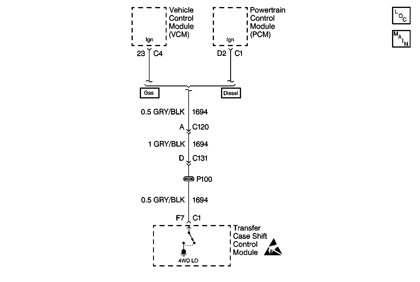
Circuit Description
CKT 1694 is used to notify the vehicle control module (VCM) powertrain control module (PCM) that the vehicle is in 4WD low range. The vehicle control module (VCM) powertrain control module (PCM) supplies 12 V on this circuit. The transfer case shift control module supplies a ground on this circuit when the vehicle is in 4WD low range.
This DTC detects an transfer case shift control module problem, a short to voltage on CKT 1694.
Conditions for Setting the DTC
| • | After the system turns the output on, (grounding CKT 1694), and reads back a high voltage, the DTC is set. The system will not attempt it again during that ignition cycle. |
| • | The transfer case shift control module reads back a high voltage when a low voltage is expected on the 4 low discrete output, CKT 1694. |
Action Taken When the DTC Sets
| • | May affect the transmission shift points. |
| • | The SERVICE indicator (AWD/4WD) lamp will be latched on for the remainder of the current ignition cycle. |
Conditions for Clearing the DTC
| • | The transfer case shift control module will clear the DTC if the condition for setting the DTC no longer exits. |
| • | A history DTC will clear after 100 consecutive ignition cycles without a fault present. |
| • | History DTCs can be cleared using a scan tool. |
Test Description
The number(s) below refer to the step number(s) on the diagnostic table.
-
This step determines if the transfer case shift control module is receiving the specified voltage from the Powertrain Control Module (PCM).
-
This step determines if circuit 1694 has a short to voltage.
Step | Action | Value(s) | Yes | No |
|---|---|---|---|---|
1 | Was the Transfer Case Diagnostic System Check performed? | -- | Go to Step 2 | Go to Transfer Case Diagnostic System Check |
Is the voltage reading within the specified values? | 11-13.5 V | Go to Step 3 | Go to Step 4 | |
3 | Replace the transfer case shift control module. Refer to Transfer Case Shift Control Module Replacement . Is the action complete? | -- | Go to Step 7 | -- |
Is the voltage reading within the specified value? | 11-13.5 V | Go to Step 5 | Go to Step 6 | |
5 | Repair a short to voltage in CKT 1694. Refer to Wiring Repairs in Wiring Systems. Is the repair complete? | -- | Go to Step 7 | -- |
6 | Replace the Powertrain Control Module (PCM). Refer to VCM Replacement/Programming for 4.3L engines or PCM Replacement/Programming 4.8L, 5.3L or 6.0L engines. Is the action complete? | -- | Go to Step 7 | -- |
7 |
Have all the ATC components been reconnected and properly mounted? | -- | Go to Step 8 | -- |
8 | Clear all ATC DTCs. Have all the ATC DTCs been cleared? | -- | Go to Transfer Case Diagnostic System Check | -- |
