Removal Procedure
- Remove the engine sight shield. Refer to Upper Intake Manifold Sight Shield Replacement .
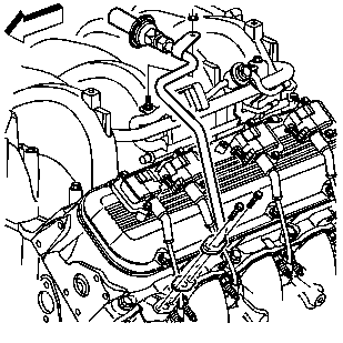
- Remove the secondary air injection (AIR) pipe nut at the fuel rail, if equipped.
- Remove the AIR pipe bolts at the exhaust manifold, if equipped.
- Disconnect the AIR pipe from the AIR pump pipe, if equipped.
- Remove the AIR pipe, if equipped.
- Remove and discard the AIR pipe gasket, if equipped.
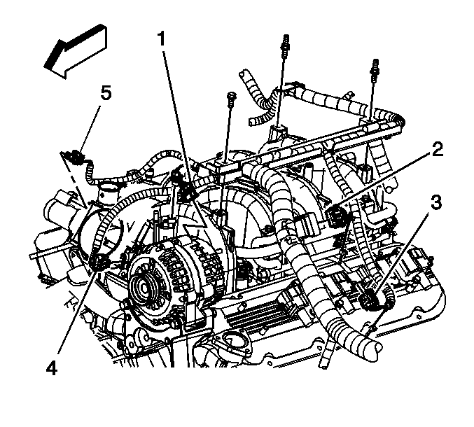
- Remove the connector position assurance (CPA) retainer from the ignition coil electrical connector (3).
- Disconnect the ignition coil harness electrical connector (3).
- Remove the spark plug wires from the spark plugs and ignition coils.
- Remove the CPA retainers at the ignition coil electrical connectors.
- Remove the ignition coil wiring harness bolts.
- Remove the ignition coil wiring harness from the rocker cover.
- Remove the valve rocker arm cover bolts.
- Remove the valve rocker arm cover.
- Inspect the valve rocker arm cover gasket for cuts or damage.
- Clean and inspect the valve rocker arm cover. Refer to Valve Rocker Arm Cover Cleaning and Inspection in Engine Mechanical - 8.1 L Unit Repair.
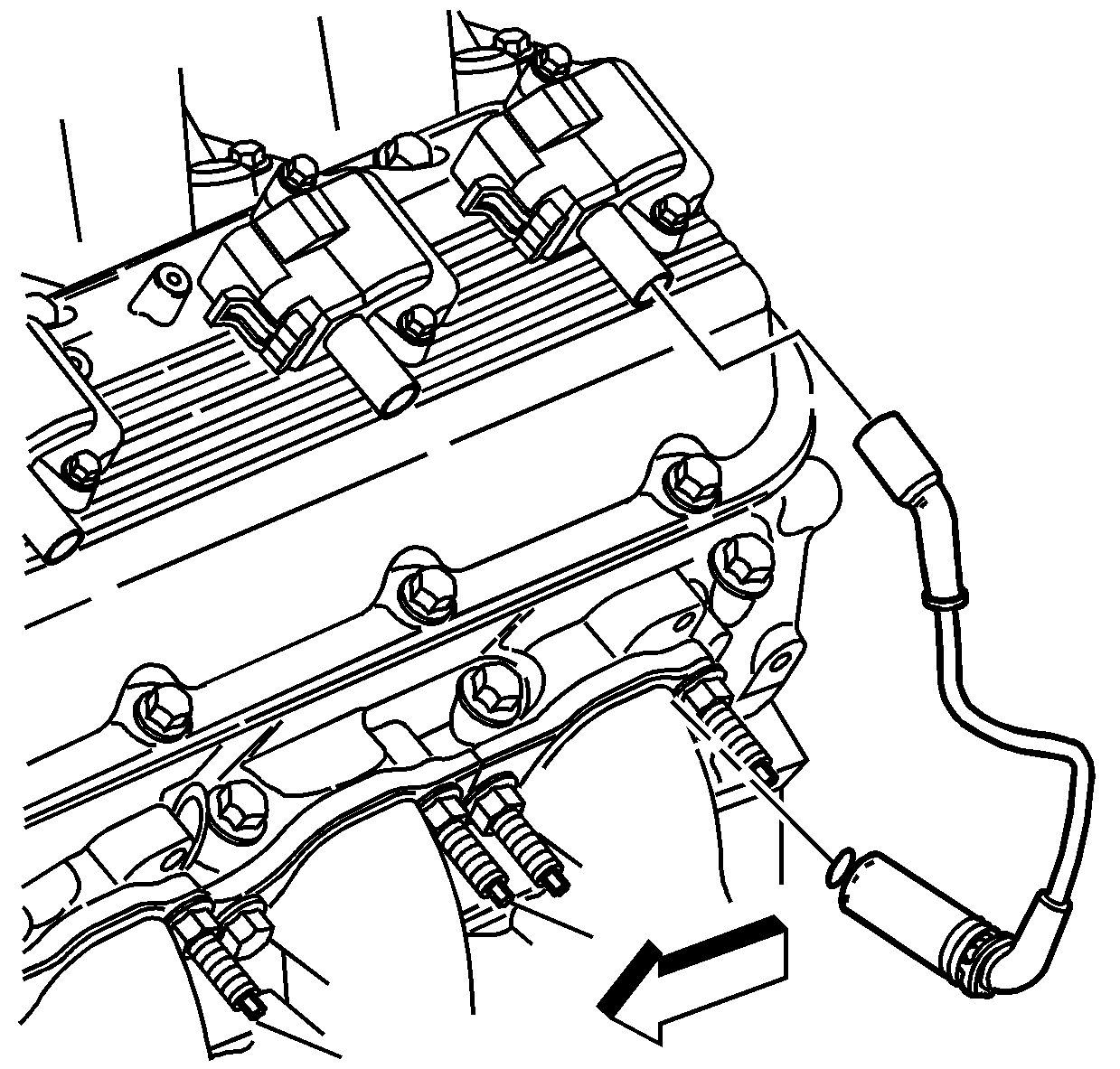
Important: Twist the spark plug boot one-half turn in order to release the boot. Pull on the spark plug boot only. Do not pull on the spark plug wire or the wire could be damaged.
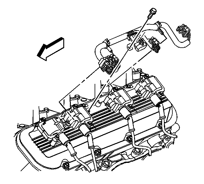
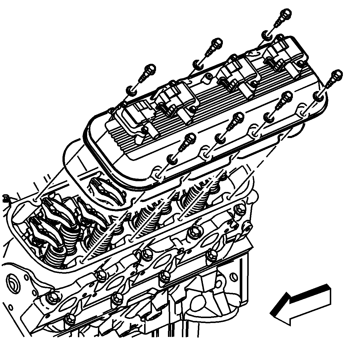
Important: Valve rocker arm cover gaskets are reusable. Replace the valve rocker arm cover gasket only if damaged.
Installation Procedure
- Install a new valve rocker arm cover gasket was removed from the rocker arm cover.
- Install the valve rocker arm cover.
- Install the valve rocker arm cover bolts.
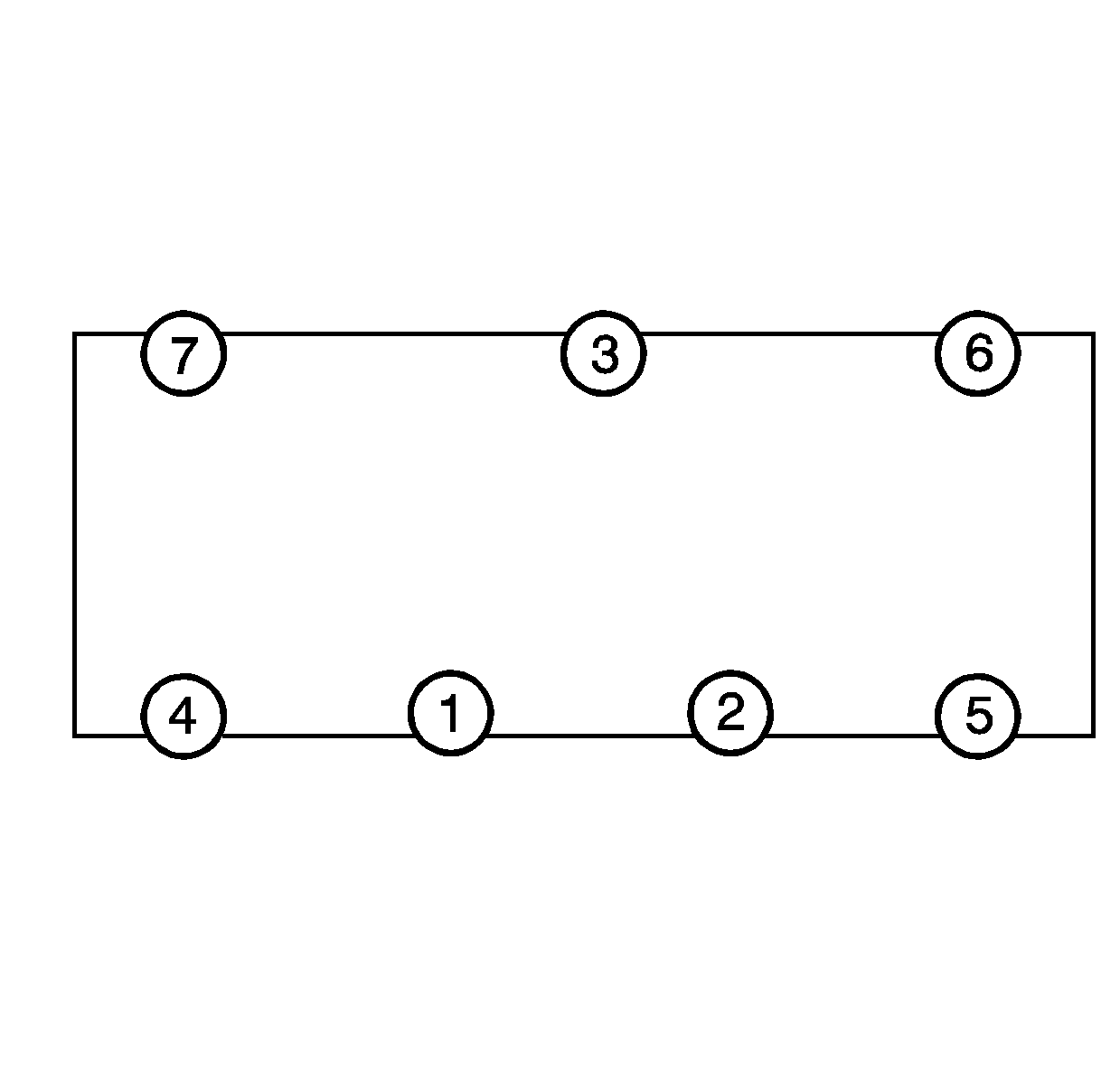
- Tighten the valve rocker arm cover bolts in sequence, using two passes as shown.
- Install the ignition coil wiring harness to the rocker cover.
- Install the ignition coil wiring harness bolts.
- Install the CPA retainers at the ignition coil electrical connectors.
- Install the spark plug wires to the spark plugs and ignition coils.
- Connect the ignition coil harness electrical connector (3).
- Install the CPA retainer to the ignition coil electrical connector (3).
- Install a NEW AIR pipe gasket, if equipped.
- Install the AIR pipe, if equipped.
- Connect the AIR pipe to the AIR pump pipe, if equipped.
- Install the AIR pipe bolts at the exhaust manifold, if equipped.
- Install the AIR pipe nut at the fuel rail, if equipped.
- Install the engine sight shield. Refer to Upper Intake Manifold Sight Shield Replacement .

Notice: Use the correct fastener in the correct location. Replacement fasteners must be the correct part number for that application. Fasteners requiring replacement or fasteners requiring the use of thread locking compound or sealant are identified in the service procedure. Do not use paints, lubricants, or corrosion inhibitors on fasteners or fastener joint surfaces unless specified. These coatings affect fastener torque and joint clamping force and may damage the fastener. Use the correct tightening sequence and specifications when installing fasteners in order to avoid damage to parts and systems.
Tighten
| • | Tighten the valve rocker arm cover bolts a first pass to 6 N·m (53 lb in). |
| • | Tighten the valve rocker arm cover bolts a final pass to 12 N·m (106 lb in). |

Tighten
Tighten the ignition coil harness bolts to 12 N·m (106 lb in).

Important: Fully install the spark plug wire by pushing on the exposed end of the spark plug boot. Do not push the spark plug wire on to the spark plug by using the metal heat shield.


Tighten
| • | Tighten the AIR pipe bolts to 25 N·m (18 lb ft). |
| • | Tighten the AIR pipe nut to 12 N·m (106 lb in). |
