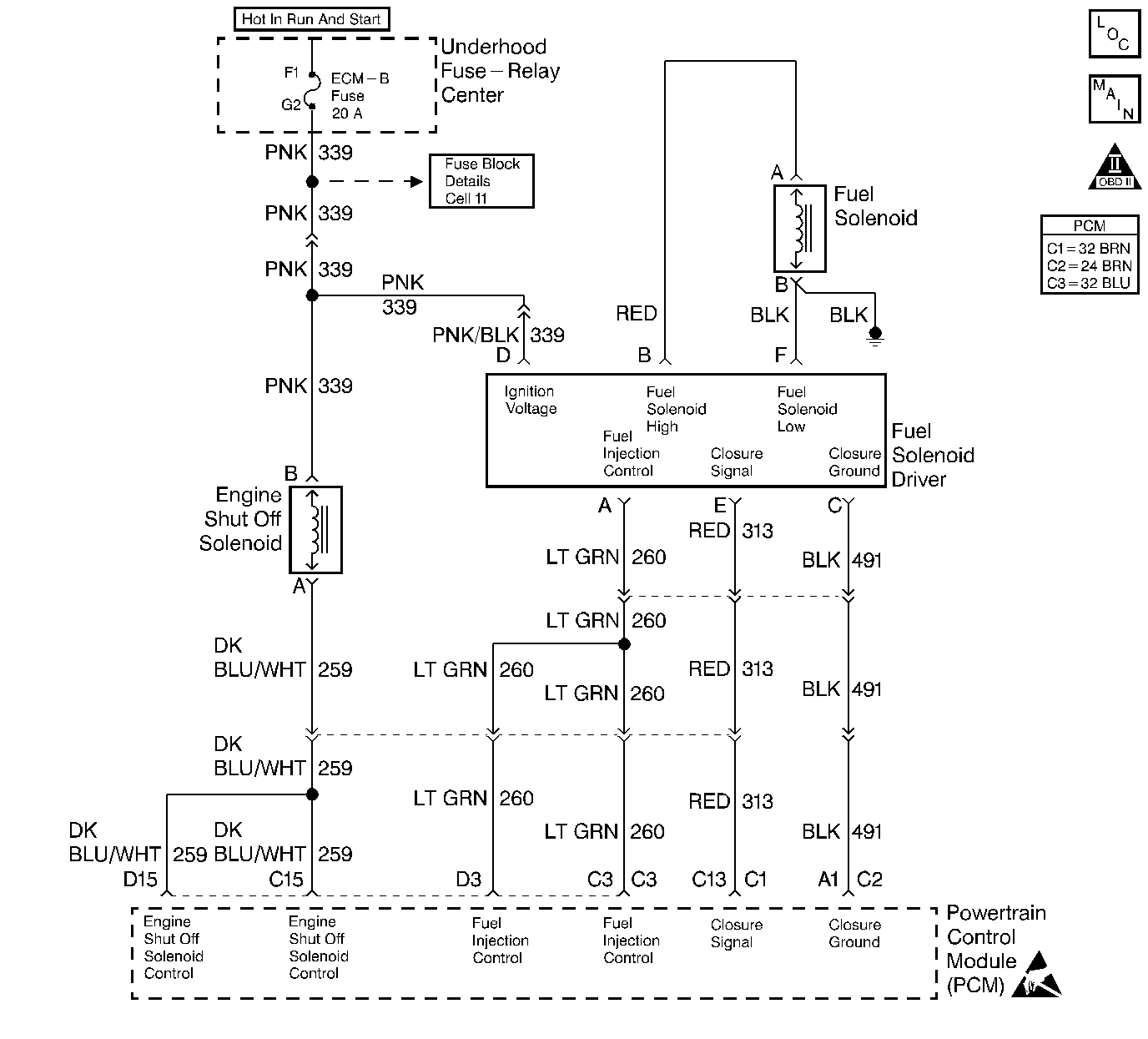
Circuit Description
The injection pump delivers fuel to individual cylinders by opening and closing a solenoid control fuel valve. The PCM monitors the amount of time it takes for the fuel solenoid valve to physically close after commanded to close. Closure time out of range is seen as a fault. This response time is measured in milli seconds.
Conditions for Setting the DTC
| • | The battery voltage greater than 12 volts and less than 15 volts. |
| • | The engine coolant temperature is greater than 50°C (122°F). |
| • | The ENGINE SPEED greater than 1350 RPM. |
| • | The requested fuel rate is greater than 0.0 mm |
| • | The Closure Time is greater than 2.5 ms. |
Action Taken When the DTC Sets
| • | The Malfunction Indicator Lamp (MIL) will not illuminate. |
| • | The PCM records the operating conditions at the time the diagnostic fails. This information stores in the Failure Records. |
Conditions for Clearing the MIL/DTC
| • | A History DTC will clear when forty consecutive warm-up cycles that the diagnostic does not fail (coolant temperature has risen 5°C (40°F) from start up coolant temperature and engine coolant temperature exceeds 71°C (160°F) that same ignition cycle. |
| • | Use of a Scan tool |
Diagnostic Aids
A weak (mechanical failure) fuel solenoid will result in a DTC P1217. If DTC P1217 is set with any other DTCs, diagnose them first. If the vehicle is running close to the DTC setting closure time, vehicle should be checked during cold start ups and during hot conditions.
Poor performance and starting conditions will exist. Fuel contamination could also cause this DTC.
Test Description
Number(s) below refer to the step number(s) on the Diagnostic Table.
-
This step determines if DTC 1217 is a hard failure or an intermittent.
-
This step will determine if the solenoid is at fault, or if there is a problem with the PCM or wiring.
Step | Action | Value(s) | Yes | No |
1 |
Important: Before clearing any DTCs, use the scan tool Capture Info to save freeze frame and failure records for reference, as the Scan tool loses data when using the Clear Info function. Was the Powertrain On-Board Diagnostic (OBD) System Check performed? | -- | ||
2 | Is DTC P0370 set? | -- | Go to DTC P0370 Timing Reference High Resolution System Performance | |
Is the scan tool display greater than the specified value? | 2.4 ms | |||
4 |
Is the voltage between specified value? | 12 - 15V | ||
5 | The DTC is intermittent. If no additional DTCs are stored, refer to Diagnostic Aids. If additional DTCs were stored refer to those DTC table(s) first. Are any additional DTCs stored? | -- | Go to the Applicable DTC Table | Go to Diagnostic Aids |
Repair the fuel solenoid driver ignition feed circuit connections or aftermarket add-ons. Refer to Notice: Connect any add-on electrically operated equipment to the vehicle's electrical system at the battery (power and ground) in order to prevent damage to the vehicle. Was a repair performed? | -- | -- | ||
7 |
Important: Before replacing the Injection pump, check for fuel system contamination. Refer to Contamination Testing Replace the Injection pump. Refer to Fuel Injection Pump Replacement Important: The new injection pump must be timed. Refer to Fuel Injection Pump Timing Adjustment Is the action complete? | -- | -- | |
8 |
Does the Scan Tool indicate the diagnostic Passed? | -- | ||
9 | Does the Scan tool display any additional undiagnosed DTCs? | -- | Go to the Applicable DTC Table | System OK |
