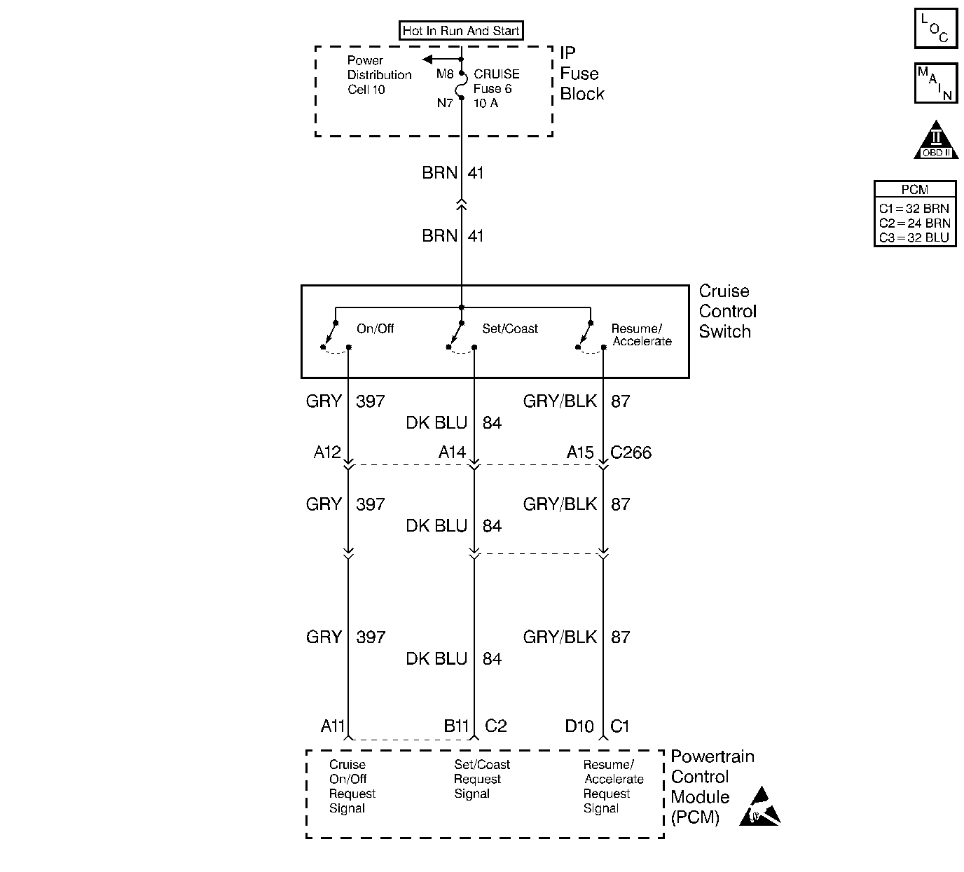
Circuit Description
The cruise control multi function lever is wired directly to the PCM. The cruise on/off, set/coast and resume/accel signals are inputs to the fuel control portion of the PCM. These inputs allow the PCM to control and hold a requested speed. The cruise can be disengaged at any time by applying the brakes. This input is sent to the PCM by the cruise control brake switch.
Diagnostic Aids
If the cruise is inoperative, and no cruise control or brake switch DTCs are stored, check for the following conditions:
| • | A malfunctioning cruise multi function switch/ wiring harness (opens or malfunctioning connections). |
| • | The clutch pedal switch is stuck in the open position. |
Other conditions that will not allow the cruise control to engage that do not pertain to the cruise system.
| • | The vehicle speed is below 25 MPH (if the cruise control is already set, the cruise will disengage at 20 MPH). |
| • | The vehicle is in 4 wheel drive low. |
| • | Any DTC that puts the vehicle in Back Up Fuel Mode (Back Up Fuel Mode affects the fuel control portion of the PCM). Refer to the appropriate DTC. |
| • | More than one accelerator pedal position (APP) DTC is set. |
Test Description
Number(s) below refer to step number(s) on the Diagnostic Table.
Step | Action | Value(s) | Yes | No |
|---|---|---|---|---|
1 | Was the Powertrain On-Board Diagnostic (OBD) System Check performed? | -- | ||
2 | Are DTCs P0501, P0567, P0568, or P0571 set? | -- | Go to the Applicable DTC Table | |
Is the test light ON? | -- | |||
4 |
Does the scan tool indicate the cruise switch is turning ON and OFF? | -- | ||
5 |
Does the scan tool indicate the set switch is turning ON and OFF? | -- | ||
6 |
Does the scan tool indicate the resume switch is turning ON and OFF? | -- | ||
7 |
Does the test light turn ON and OFF with each cruise control ON/OFF switch cycle? | -- | ||
8 |
Does the test light turn ON and OFF with each cruise control ON/OFF switch cycle? | -- | ||
9 |
Does the test light turn ON and OFF with each cruise control set/coast switch cycle? | -- | ||
10 |
Does the test light turn ON and OFF with each cruise control set/coast switch cycle? | -- | ||
11 |
Does the test light turn ON and OFF with each cruise control resume/accelerate switch cycle? | -- | ||
12 |
Does the test light turn ON and OFF with each cruise control resume/accelerate switch cycle? | -- | ||
13 |
Was a problem found? | -- | ||
14 | Repair the open in the ignition feed circuit. Is the action complete? | -- | -- | |
15 | Repair the open or short to ground in the cruise ON/OFF request signal circuit. Is the action complete? | -- | -- | |
16 | Repair the open or short to ground in the cruise set/coast request signal circuit. Is the action complete? | -- | -- | |
17 | Repair the open or short to ground in the cruise resume/accelerate request signal circuit. Is the action complete? | -- | -- | |
18 | Replace the cruise control switch. Is the action complete? | -- | -- | |
19 |
Was a problem found? | -- | ||
20 | Replace the PCM. Important: The new PCM must be programmed. Refer to Powertrain Control Module Replacement/Programming . Is the action complete? | -- | -- | |
21 | Operate the vehicle within the conditions under which the original problem was noted. Does the system operate properly? | -- | System OK |
