Purpose
The function of the fuel metering system is to deliver the correct amount of fuel to the engine under all operating conditions.
Fuel is delivered to the engine by individual fuel injectors and poppet nozzles mounted in the intake manifold near each cylinder.
Fuel Metering System Components
The fuel metering system consists of the following parts:
| • | The fuel supply components, such as fuel tanks, pumps, pipes |
| • | The fuel pump electrical circuit |
| • | The fuel meter body assembly |
| • | The fuel injectors and poppet nozzles |
| • | The fuel pressure regulator |
| • | The throttle body |
| • | The idle air control (IAC) valve |
| • | The throttle position (TP) sensor |
Fuel Supply Components
The fuel supply is stored in the fuel tank. An electric fuel pump attaches to the fuel sender assembly inside the fuel tank. The fuel pump pumps fuel through an in-line fuel filter to the fuel meter body assembly. The pump provides fuel at a pressure greater than is needed by the injectors. The fuel pressure regulator, part of the fuel meter body assembly, keeps fuel available to the injectors at a regulated pressure. A separate fuel return pipe returns the unused fuel to the fuel tank.
Fuel Pump Electrical Circuit
When the ignition switch is in the ON position, before engaging the starter, the control module energizes the fuel pump relay for 2 seconds causing the fuel pump to pressurize the fuel system. If the control module does not receive the ignition reference pulses, engine cranking or running, within 2 seconds, the control module shuts off the fuel pump relay, causing the fuel pump to stop. The control module will also turn ON the fuel pump for 2 seconds when the ignition switch is turned to the OFF position.
Fuel Meter Body Assembly
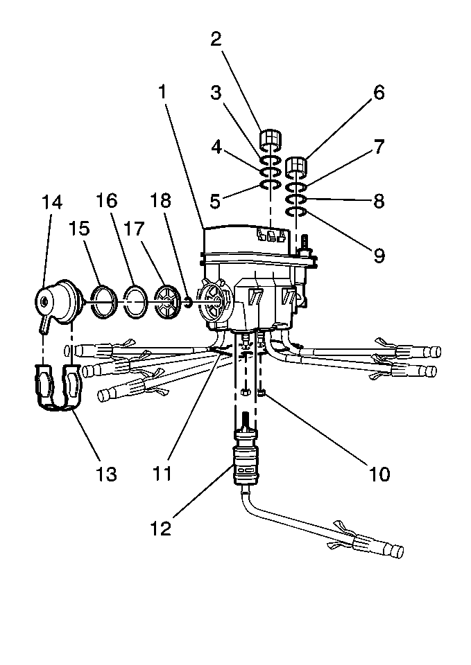
The fuel meter body assembly (1) attaches to the lower intake manifold. The fuel meter body assembly performs the following functions:
| • | It distributes fuel evenly to the injectors (12). |
| • | It integrates the fuel pressure regulator (14) into the fuel metering system. |
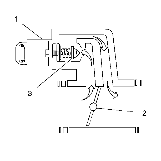
Injector and Poppet Nozzle Assembly
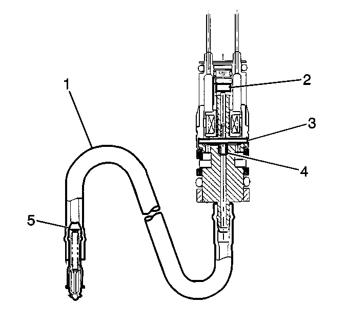
Each fuel injector assembly is a solenoid-operated device, controlled by the control module. The fuel injector assembly meters the pressurized fuel through a poppet nozzle valve (5) to a single engine cylinder. The control module energizes the flow control solenoid (2), which opens an armature valve (3), allowing fuel to flow past the valve and through a flexible fuel pipe (1) to the poppet nozzle valve. An increase in fuel pressure causes the poppet nozzle ball to open from its seat against the extension spring force. This allows the fuel to flow from the nozzle.
De-energizing the flow control solenoid (2) closes the armature valve (3). De-energizing the solenoid also reduces the fuel pressure acting on the poppet nozzle ball. The extension spring closes the ball to the seat. The extension spring also checks the pressure between the ball and seat of the poppet nozzle valve (5) and the injector armature (3) and seat (4).
Fuel Pressure Regulator Assembly
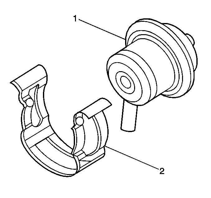
The fuel pressure regulator (1) is a diaphragm-operated cartridge type relief valve with the fuel pump pressure on one side and the regulator spring pressure and intake manifold vacuum on the other side. A retainer clip (2) holds the fuel pressure regulator in the fuel meter body assembly. The fuel pressure regulator maintains a constant pressure differential across the injectors at all times. The pressure regulator compensates for engine load by increasing the fuel pressure as engine vacuum drops.
Throttle Body Assembly
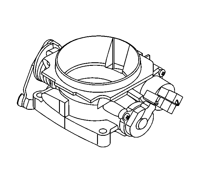
The throttle body attaches to the upper intake manifold. The throttle body controls the air flow into the engine, thereby controlling the engine output. The vehicle operator opens the throttle valve within the throttle body through the accelerator controls. During engine idle, the throttle valve is almost closed. A fixed air bypass orifice and the idle air control (IAC) valve handle the air flow control. The throttle body also provides the location for mounting the Throttle Position (TP) sensor.
Idle Air Control (IAC) Valve Assembly
The purpose of the IAC valve assembly is to control the engine idle speed while preventing engine stalls due to changes in the engine load. The IAC valve (1), mounted in the throttle body assembly, controls the bypass air around the throttle valve (2). By moving a conical valve known as a pintle (3) in toward the seat, in order to decrease the air flow, or out away from the seat, in order to increase the air flow, a controlled amount of air moves around the throttle valve. If the engine speed is too low, more air is bypassed around the throttle valve in order to increase the RPM. If the engine speed is too high, less air is bypassed around the throttle valve in order to decrease the RPM. The control module moves the IAC valve in small steps, called counts. These can be displayed by a scan tool, which plugs into the data link connector (DLC).
The control module calculates the proper position of the IAC valve during idle based on the battery voltage, the engine coolant temperature, the engine load, and the engine RPM. If the RPM drops below specification and the throttle valve is closed, the control module senses a near stall condition and calculates a new valve position in order to prevent stalling.
Throttle Position (TP) Sensor
The TP sensor attaches to the side of the throttle body opposite the throttle lever. The TP sensor senses the throttle valve angle and relays that information to the control module. The control module requires knowledge of throttle angle in order to generate the required injector control signals or pulses.
