For 1990-2009 cars only
Tools Required
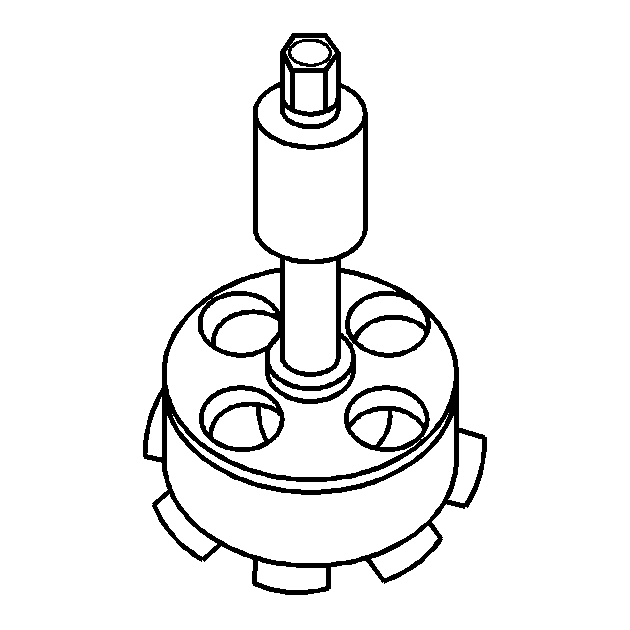
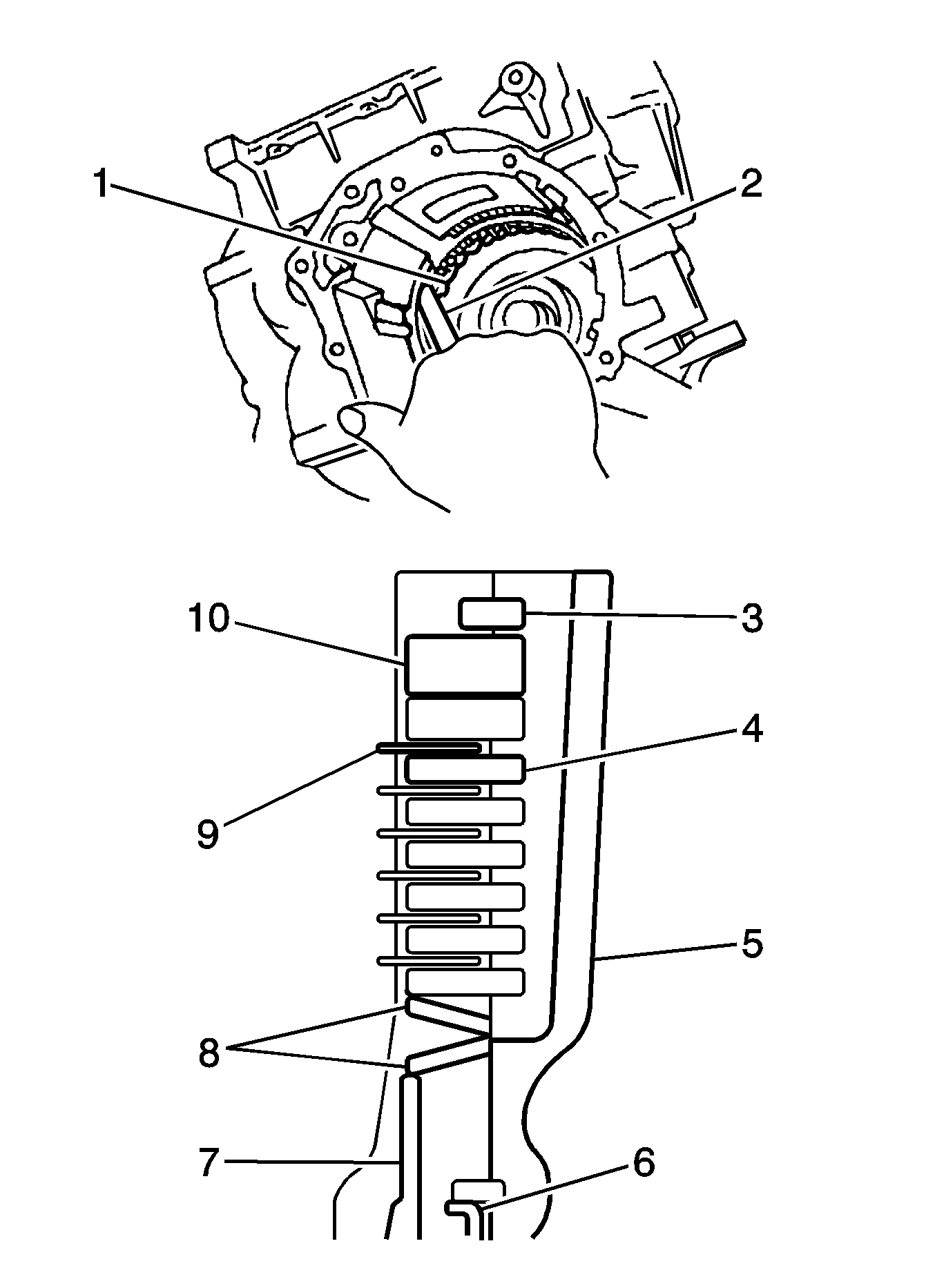
DT 47526 (DW 260-210) Low & Reverse Brake Spring Compressor
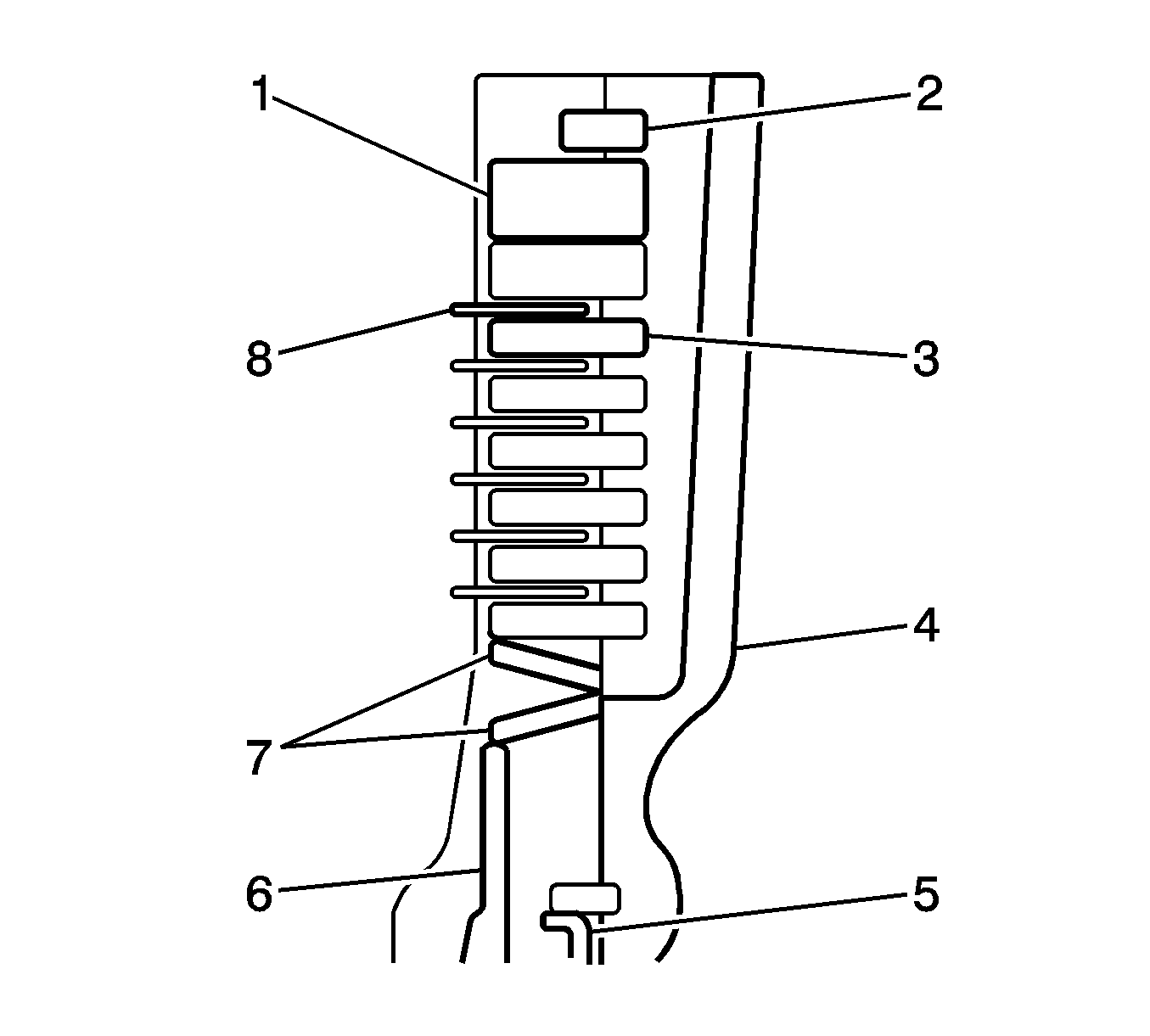
- Replace the O-ring with a new one. Apply AT fluid to the new O-ring, and then install it in the low clutch piston.
- Be careful not to twist or misalign out the O-ring when inserting the low & reverse clutch piston.
- Assemble with the cushion plate periphery touching the low & reverse clutch.
- Be sure to assemble the low & reverse brake plate set components in the right order as indicated.
- Be careful not to distort the spring retainer when using DT 47526 (1).
- Ensure that the snap ring fits snugly in the drum groove.
- Ensure that the snap ring opening is not aligned with the stopper.
- Ensure that the snap ring opening is aligned with the concave aperture.
- Before using a new low & reverse brake plate set, soak it in AT fluid for more than 2 hours.
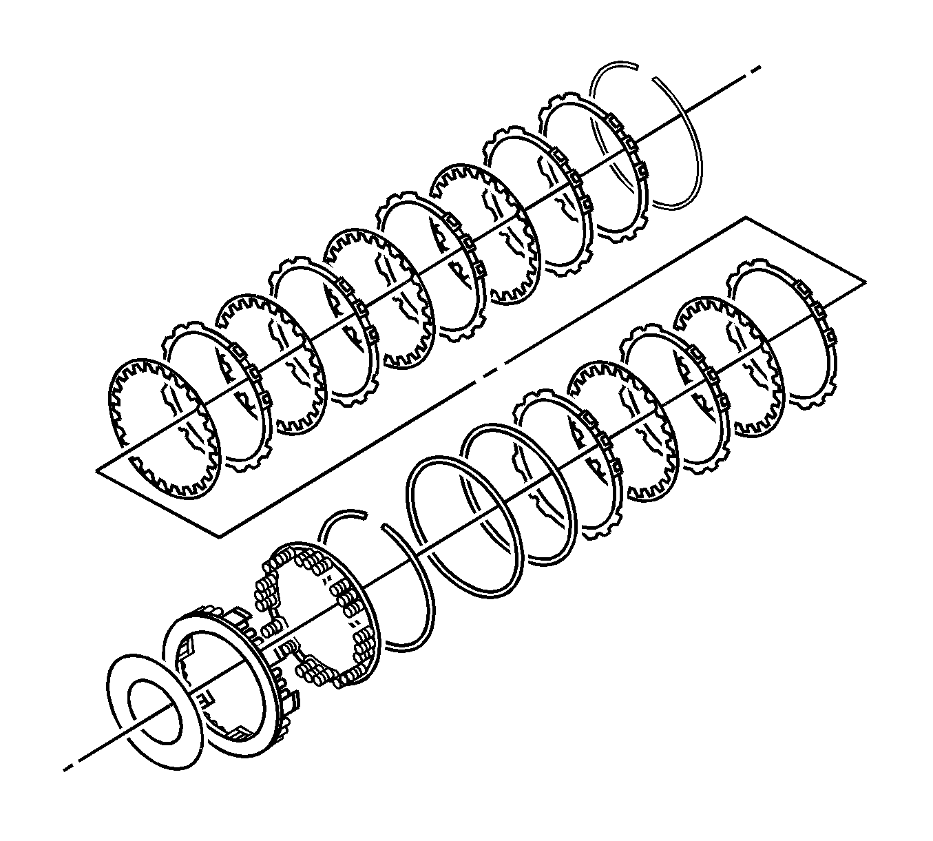
Important: Note the direction of the cushion plate.
| • | Snap ring (2) |
| • | Retaining plate (1) |
| • | Friction plates ( 8) |
| • | Separator plates (3) |
| • | Case (4) |
| • | Cushion plates (7) |
| • | Piston (6) |
| • | Return spring (5) |
Operational Check
- Using a thickness gage (2), measure the clearance between the snap ring and the retaining plate (10).
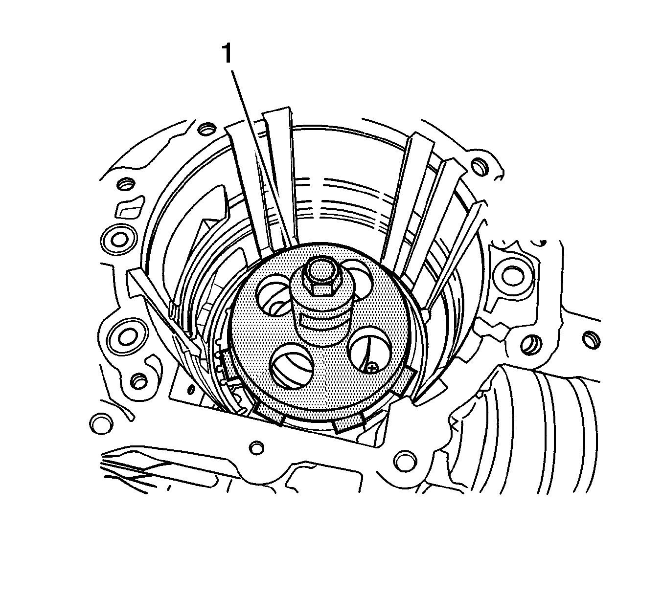
- Blow air into the oil inlet (2) of the control valve installation face, and check the functioning of the piston.
Important: If the application limit is exceeded, replace the friction (9) and separator plates (4) with new ones, and select a suitable retaining plate (10) so that the specified clearance will be obtained.
If the clearance is less than the application limit, select a suitable retaining plate (10) so that the clearance will fall within the desired range.Clearance Specification
Specification standard is 0.8-1.1 mm (0.03-0.04 in).
Clearance Specification
Specification application limit is 1.3 mm (0.05 in).
Caution: Refer to Safety Glasses and Compressed Air Caution in the Preface section.
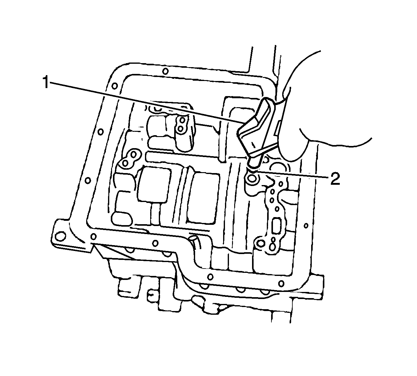
Important: Close the other holes when blowing air using an air gun.
