Tools Required
| • | J 44247
Internal Wiring Harness Installer |
| • | J 44257
Main Wiring Harness Connector Remover |
Removal Procedure
Caution: Unless directed otherwise, the ignition and start switch must be in the OFF or LOCK position, and all electrical loads must be OFF before servicing
any electrical component. Disconnect the negative battery cable to prevent an electrical spark should a tool or equipment come in contact with an exposed electrical terminal. Failure to follow these precautions may result in personal injury and/or damage to
the vehicle or its components.
- Remove the oil pan and transmission internal oil filter. Refer to
Oil Pan Replacement
.
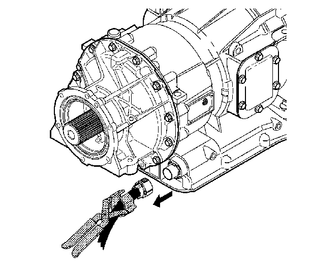
- Disconnect the external wiring harness from the main transmission connector. Use
J 44257
, if connector is not easily accessible.
Important: The main transmission connector is actually one end of the internal wiring harness that protrudes through the transmission case.
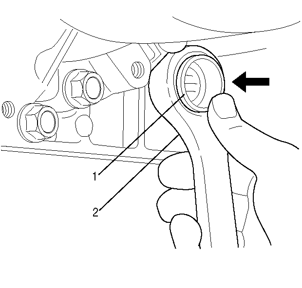
- Place a 30 mm or 1 3/16 inch 12-point deep socket or box-end wrench (2) over the main transmission connector (1).
- Push inward on the socket or wrench to release the retaining feet that attach the connector (1) to the transmission case.
- Remove the wrench. Push inward on the electrical connector to separate from the transmission case.
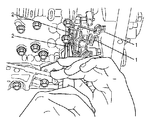
- Disconnect the internal wiring harness connectors (1) from the solenoids, the internal mode switch (IMS), and from
the transmission fluid pressure (TFP) switch.
Important: The solenoid retainers for shift solenoid 3 (SS3) and shift solenoid 2 (SS2) also retain tabs on the wiring harness U-channel. The solenoids will remain in position even after the solenoid
retainers are removed.
- Remove the solenoid retainers (2) for SS3 and SS2.
- Remove the internal wiring harness from the transmission.
Installation Procedure
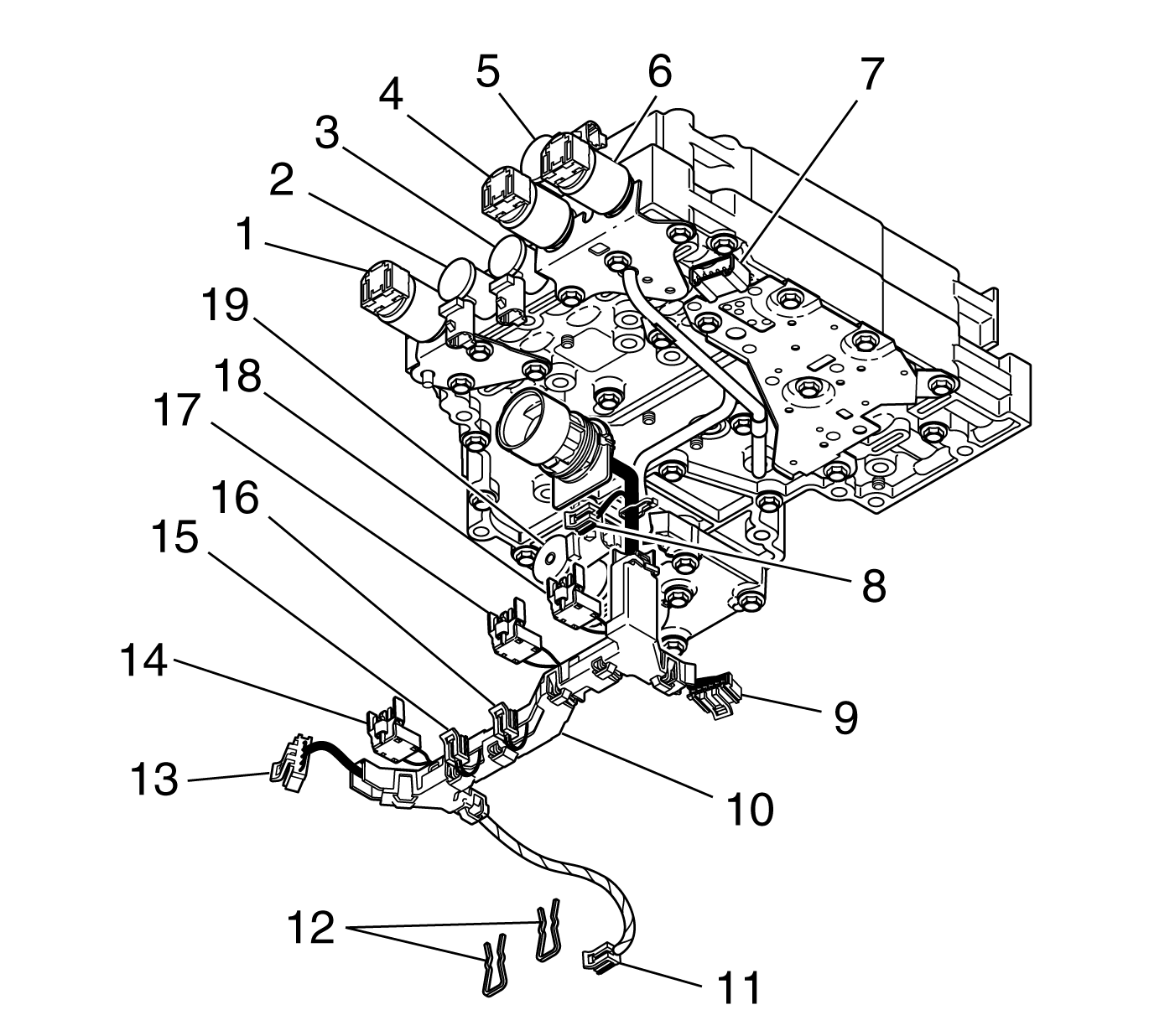
- Align the tabs on the new wiring harness (10)
U-channel with the solenoid retainer slots for SS3 (3) and SS2 (2) on the control valve assembly. Install the solenoid retainers (12) for the SS3 (3) and SS2 (2) solenoids.
Important: The internal wiring harness connectors should be in the correct position for installation because of their pre-assembled position in the U-channel.
- Attach the internal wiring harness (10) connectors to the solenoids, the IMS, and the TFP switch.
| • | Connector (8) goes to SS1 (5) |
| • | Connector (9) goes to the TFP switch (7) |
| • | Connector (11) goes to the MAIN MOD solenoid (19) |
| • | Connector (13) goes to the IMS |
| • | Connector (14) goes to the TCC PCS (1) |
| • | Connector (15) goes to SS2 (2) |
| • | Connector (16) goes to SS3 (3) |
| • | Connector (17) goes to PCS1 (4) |
| • | Connector (18) goes to PCS2 (6) |
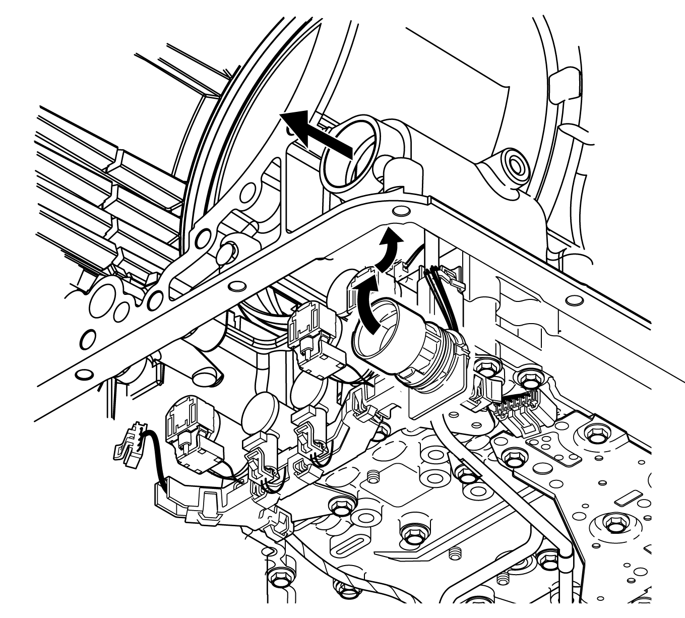
- Push the main transmission connector (2)
outward through hole (1) in the transmission case until the retaining feet on the connector are near the locked position.
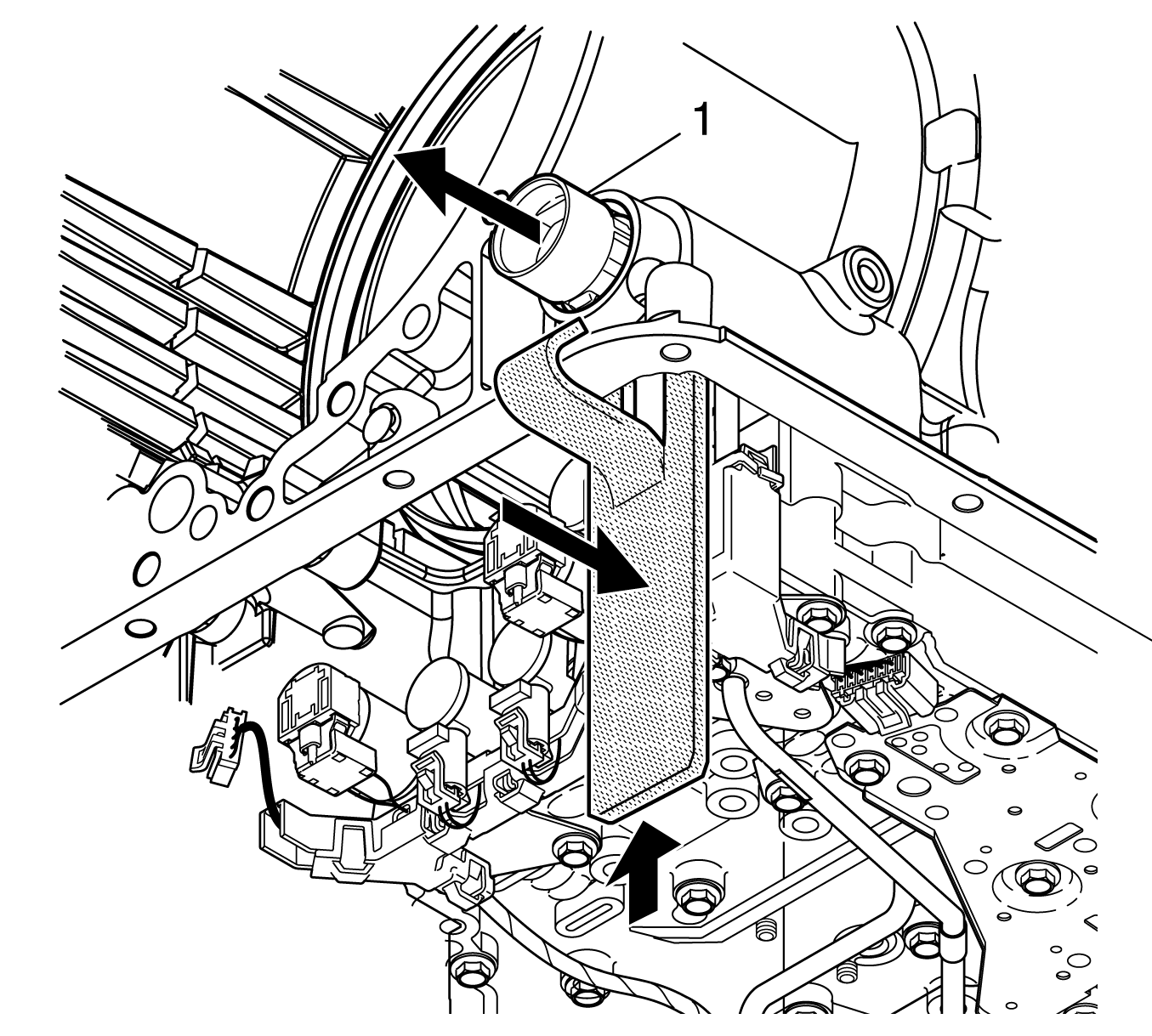
- Use
J 44247
to seat the retaining feet on transmission connector (1).
- Install the oil pan and transmission internal oil filter. Refer to
Oil Pan Replacement
.
- Connect the external wiring harness to the main transmission connector.
Important: The FastLearn, adapt, procedure must be performed. This can be done in 1 step using a scan tool. If this procedure is not done, the TCM adaptive values will be at the settings that it learned for the old components
and will be in slow adaptive mode. Under these conditions, it will take an unacceptably long time for the adaptive values to converge to levels suitable for the new transmission.
- Perform the FastLearn procedure. Refer to
FastLearn Procedure
.


