For 1990-2009 cars only
Special Tools
J 42640 Steering Column Anti-rotation Pin
Removal Procedure
- Verify the following before removing the inflatable restraint steering wheel module coil:
- Remove the steering wheel. Refer to Steering Wheel Replacement .
- Remove the steering column shroud. Refer to Steering Column Shroud Replacement .
- Disconnect any electrical connectors as needed.
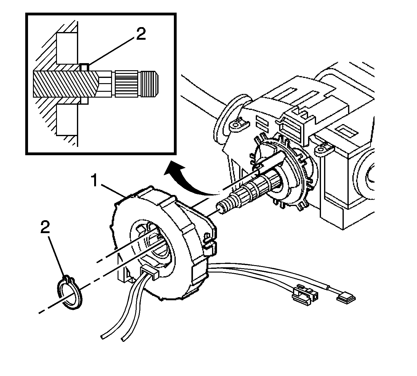
- Remove the inflatable restraint steering wheel module coil retaining ring (2) and discard it. DO NOT reuse the ring.
- Remove the inflatable restraint steering wheel module coil (1) from the steering shaft.
- If replacing, discard the old inflatable restraint steering wheel module coil.
Notice: The wheels of the vehicle must be straight ahead and the steering column in the LOCK position before disconnecting the steering column or intermediate shaft from the steering gear. Failure to do so will cause the SIR coil assembly to become uncentered, which may cause damage to the coil assembly.
| • | The wheels on the vehicle are straight ahead. |
| • | That anti-rotation pin J 42640 is installed or the ignition and start switch is in the LOCK position. |

Installation Procedure
- If reusing the existing inflatable restraint steering wheel module coil it MUST be centered. Refer to Inflatable Restraint Steering Wheel Module Coil Centering .
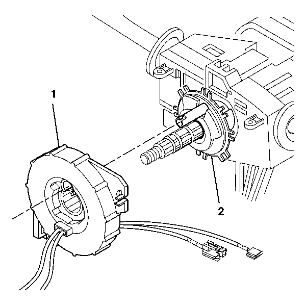
- Align the inflatable restraint steering wheel module coil (1) with the horn tower on the turn signal switch cancel cam (2).
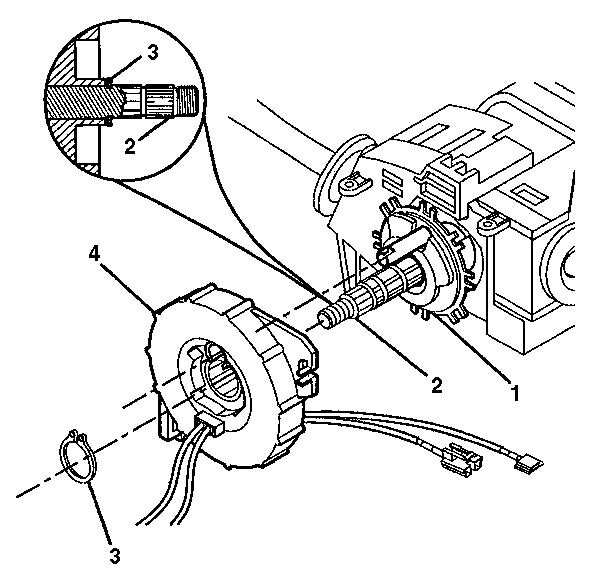
- Slide the inflatable restraint steering wheel module coil (4) onto the steering shaft (2).
- Firmly seat the new inflatable restraint steering wheel module coil retaining ring (3) into the appropriate groove on the steering shaft (2).
- Remove and discard the centering tab from the new inflatable restraint steering wheel module coil (4).
- Connect any electrical connectors as needed.
- Install the steering column shroud. Refer to Steering Column Shroud Replacement .
- Install the steering wheel. Refer to Steering Wheel Replacement .
- Remove anti-rotation pin J 42640 .
Notice: The new SIR coil assembly will be centered. Improper alignment of the SIR coil assembly may damage the unit, causing an inflatable restraint malfunction.
Important: Do not remove the centering tab from the new inflatable restraint steering wheel module coil until the installation is complete. If the centering tab is missing then re-center the assembly.


